
Multifunctional cutting machine capable of conveniently cutting pipeline in wall

An inner-pipe, multi-function technology, applied in the field of multi-function cutting machines, can solve problems such as pipe damage, lack of cutting safety, inability to ensure cutting quality, etc., to improve cutting efficiency, flexibility, and ensure cutting quality and safety. Effect

Inactive Publication Date: 2021-01-19
王祎颖
View PDF0 Cites 2 Cited by
  • Summary
  • Abstract
  • Description
  • Claims
  • Application Information

AI Technical Summary

Problems solved by technology

[0002] Existing pipes, such as PC plastic pipes and stainless steel pipes, need to be cut to a certain length when they are used. However, the current cutting method is to cut them on the cutting machine in advance, and then use them at the construction site. Due to the There are various uncertain factors at the time, so the length of the pipeline needs to be adjusted back and forth. The existing cutting machine cannot process the pipeline conveniently and quickly at the construction site. In addition, although the existing cutting machine has a small hand-held type, but this type of cutting machine can only cut pipes with small diameters due to the small cutting blade, and it cannot be positioned when this type of cutting machine is cutting, especially when cutting pipes in the wall, the suspended hand-held cutting machine Cutting is very easy to cause damage to the pipeline, the cutting quality cannot be ensured, and the safety of cutting is even less

Method used


Image

  • Multifunctional cutting machine capable of conveniently cutting pipeline in wall
  • Multifunctional cutting machine capable of conveniently cutting pipeline in wall
  • Multifunctional cutting machine capable of conveniently cutting pipeline in wall

Examples


Embodiment Construction

[0021] The implementation of the present invention will be illustrated by specific specific examples below, and those skilled in the art can easily understand other advantages and effects of the present invention from the content disclosed in this specification. The "above" and "below" mentioned in this embodiment are consistent with the directions above and below the drawings themselves, which are only for the convenience of description and clarification, and are not used to limit the scope of the present invention, and the changes or adjustments of their relative relationships , without substantively changing the technical content, it should also be regarded as the scope of the present invention that can be implemented.

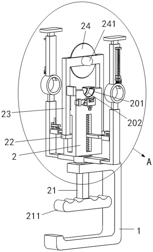
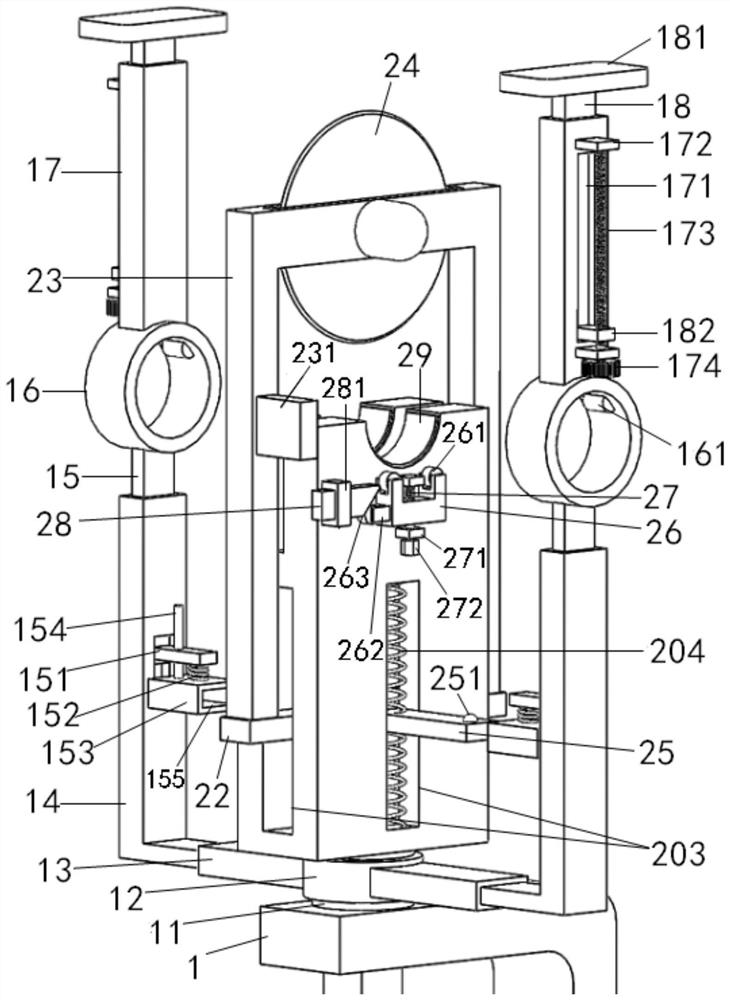
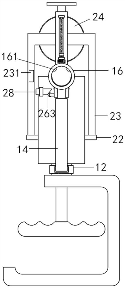
[0022] Depend on Figure 1 to Figure 4 As shown, a multifunctional cutting machine that is convenient for cutting pipes in walls includes a hand-held frame 1, a circular seat 11 is fixed on the top surface of the top plate of the hand-held frame 1, and a cu...


PUM


Abstract

The invention discloses a multifunctional cutting machine capable of conveniently cutting a pipeline in a wall. The multifunctional cutting machine comprises a handheld frame, a circular base and a cutting main body base are fixed to the handheld frame, an arc-shaped containing groove and a cutting groove are formed in the top face of the cutting main body base, a main driving rod is inserted intothe cutting main body base, a pair of transmission plates arranged on the left side and the right side of the top of the main driving rod extend out of the cutting main body base and are connected with a cutting frame, and a cutting blade and a cutting motor are arranged in a top plate of the cutting frame. The multifunctional cutting machine has the advantages that the cutting blade and a pressing ring can move at the same time by pulling the main driving rod, so that the purpose that the pipeline can be automatically pressed during cutting and can be automatically loosened after cutting isachieved, the cutting efficiency is greatly improved, when the pipeline in the wall is cut, two movable frames can be flexibly attached to the wall, the stability of the whole device is ensured, adjustable limiting roll shafts are arranged on the cutting main body base and the pressing ring, so that the pipeline with a relatively large diameter can be subjected to ring type cutting, and the flexibility is high.

Description

Technical field: [0001] The invention relates to the technical field of pipe cutting, in particular to a multifunctional cutting machine for cutting pipes in walls. Background technique: [0002] Existing pipes, such as PC plastic pipes and stainless steel pipes, need to be cut to a certain length when they are used. However, the current cutting method is to cut them on the cutting machine in advance, and then use them at the construction site. Due to the There are various uncertain factors at the time, so the length of the pipeline needs to be adjusted back and forth. The existing cutting machine cannot process the pipeline conveniently and quickly at the construction site. In addition, although the existing cutting machine has a small hand-held type, but this type of cutting machine can only cut pipes with small diameters due to the small cutting blade, and it cannot be positioned when this type of cutting machine is cutting, especially when cutting pipes in the wall, the ...

Claims


Application Information

Patent Timeline
Patent Type & Authority Applications(China)
IPC IPC(8): B23D21/00B23D33/02
CPCB23D21/00B23D33/02
Inventor 王祎颖丁佳伟
Owner 王祎颖
Learn More