Supercharge Your Innovation With Domain-Expert AI Agents!

Cold-pad-batch ultrasonic dyeing machine and dyeing method

An ultrasonic and dyeing machine technology, applied in the field of textile printing and dyeing, can solve the problems of late start of cold pad batch dyeing process research, defects that cannot be corrected in time, and difficult control of shade, so as to shorten dyeing time, save dye cost, and improve efficiency. The effect of color ratio

Pending Publication Date: 2021-01-19
连云港创美机械有限公司
View PDF4 Cites 2 Cited by
  • Summary
  • Abstract
  • Description
  • Claims
  • Application Information

AI Technical Summary

Problems solved by technology

[0003] In our country, due to the influence of many factors such as equipment and dyes, the research on the process of cold pad batch dyeing started relatively late.
In recent years, with the introduction of imported equipment and dyestuffs and the continuous efforts of domestic equipment manufacturers and dyestuff manufacturers, the equipment and dyestuffs used for cold dyeing can fully meet the production needs, so more and more cold pad-batch dyeing processes It has attracted the attention of many domestic printing and dyeing enterprises. In the current situation where printing and dyeing enterprises are facing increasing energy costs and the internal quality requirements of export products, it is a wise consideration to use cold pad batch dyeing technology. However, cold pad batch The dyeing process also has shortcomings, such as the shade is not easy to control, and the defects in the dyeing process cannot be corrected in time, etc.

Method used


Image

  • Cold-pad-batch ultrasonic dyeing machine and dyeing method

Examples


Embodiment Construction

[0030] In order to make the purpose, technical solutions and advantages of the embodiments of the present invention clearer, the following will clearly and completely describe the technical solutions in the embodiments of the present invention in conjunction with the accompanying drawings of the present invention. Obviously, the described embodiments are part of the present invention Examples, not all examples. Based on the embodiments of the present invention, all other embodiments obtained by persons of ordinary skill in the art without making creative efforts belong to the protection scope of the present invention.

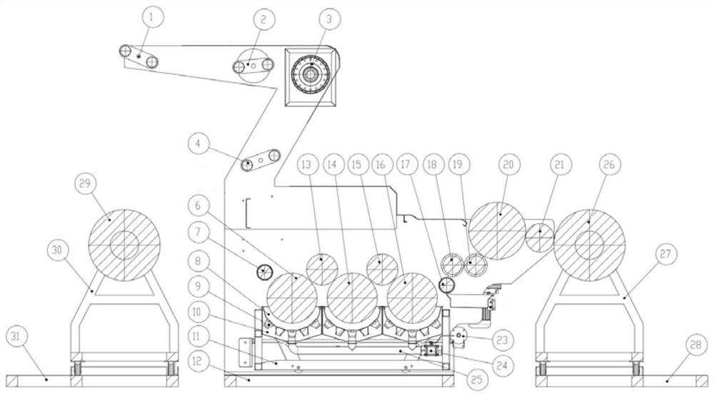
[0031] refer to figure 1 , a cold pile ultrasonic dyeing machine, the dyeing machine includes a discharging mechanism, a dyeing mechanism and a receiving mechanism;

[0032] Described discharging mechanism comprises discharging base 31 and the discharging rack 30 that is fixedly installed on the discharging base 31, and the discharging shaft 29 that is conveni...


PUM


Abstract

Disclosed is a cold-pad-batch ultrasonic dyeing machine. The cold-pad-batch ultrasonic dyeing machine comprises a discharging mechanism, a dyeing mechanism and a collecting mechanism. The dyeing mechanism comprises a dyeing frame; an ultrasonic dyeing box is arranged on the dyeing frame; an input mechanism used for conveying rolled cloth on the discharging mechanism to the ultrasonic dyeing box isarranged on the dyeing frame on the side of the discharging mechanism; an output mechanism used for conveying the dyed cloth to the collecting mechanism is arranged on the dyeing frame on the side ofthe collecting mechanism; a liquid rolling mechanism for performing uniform liquid rolling on the dyed cloth is arranged on the dyeing frame on the collecting side; and a plurality of groups of ultrasonic dyeing pools are sequentially arranged in the ultrasonic dyeing box, and an ultrasonic vibrator box is mounted in each group of ultrasonic dyeing pools. The dyeing machine is reasonable in design, high in integration degree, capable of conducting cold-pad-batch ultrasonic dyeing on cotton cloth and other fabrics, high in dyeing effect and efficiency, capable of effectively improving production efficiency and capable of saving production cost.

Description

[0001] The invention relates to the technical field of textile printing and dyeing, in particular to a cold-batch ultrasonic dyeing machine, and also relates to a dyeing method of the above-mentioned cold-batch ultrasonic dyeing machine. Background technique [0002] Cold pad-batch dyeing is a brand-new open-width dyeing process. This dyeing process originated in Europe. Because this dyeing process has high color fixation rate, good color fastness, energy saving, pollution reduction, convenient equipment maintenance and suitable for small Therefore, by the end of the 1980s, this new technology was popular in printing and dyeing enterprises in various European countries. [0003] In our country, due to the influence of many factors such as equipment and dyes, the research on the process of cold pad-batch dyeing started relatively late. In recent years, with the introduction of imported equipment and dyestuffs and the continuous efforts of domestic equipment manufacturers and dy...

Claims


Application Information

Patent Timeline
Patent Type & Authority Applications(China)
IPC IPC(8): D06B13/00D06B3/18D06B23/02
CPCD06B13/00D06B3/18D06B23/02
Inventor 伏勇伏邦源李纪灵
Owner 连云港创美机械有限公司
Features
  • R&D
  • Intellectual Property
  • Life Sciences
  • Materials
  • Tech Scout
  • Unparalleled Data Quality
  • Higher Quality Content
  • 60% Fewer Hallucinations
Learn More