
Method and device for measuring drilling depth through water level

A technology for measuring borehole depth and water level, which can be used in surveying, earthwork drilling, water resources assessment, etc. It can solve the problems of drilling rig sticking rods, drill pipe sticking, inaccurate drilling depth measurement data, etc., and solve human errors , increase work costs, and reduce the effect of human measurement errors

Active Publication Date: 2021-01-19
深圳市城安物联科技有限公司
View PDF7 Cites 1 Cited by
  • Summary
  • Abstract
  • Description
  • Claims
  • Application Information

AI Technical Summary

Problems solved by technology

[0002] When the drilling rig is in operation, it needs to measure the depth of its drilling. The existing measurement method is to determine the number of drill pipes drilled by detecting the reciprocating times of the drilling rig, and then determine the drilling depth. Rod, that is, the drilling rig reciprocates normally but the drill pipe is stuck. At this time, continuing to count will affect the actual drilling depth statistics, and prevent fraudulent behavior caused by inadequate on-site supervision, such as over-reporting or falsely reporting the number of meters. Reciprocating and idling occurs, resulting in inaccurate measurement data of the actual drilling depth

Method used


Image

  • Method and device for measuring drilling depth through water level
  • Method and device for measuring drilling depth through water level

Examples


Embodiment 1

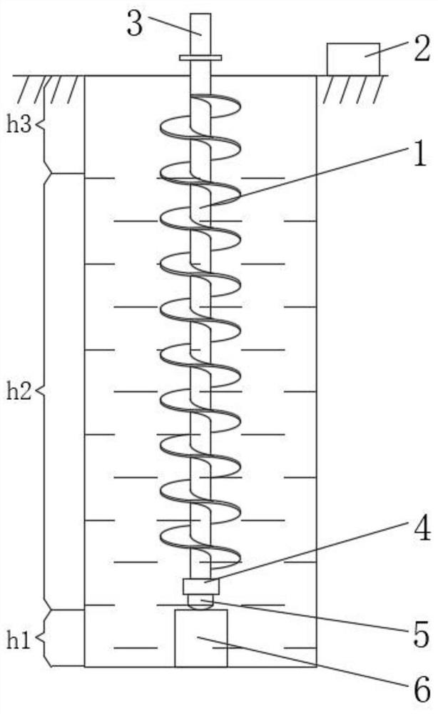
[0037] A method for measuring the depth of a borehole with a water level, the method comprising the steps of:

[0038] (1) First measurement: measure the height of the rock and soil sampling device, and define the height as h1;

[0039] (2) Secondary measurement: use the mud pump to transport the mud in the mud pool to the hole through the drill pipe, and measure the height from the mud surface in the hole to the ground, which is defined as h3;

[0040] (3) Instrument installation: install the water level gauge and acquisition device on the drill pipe;

[0041] (4) Data acquisition: After the installation is completed, the drilling operation starts. During the drilling process, when the pressure value reaches the preset value, the water level gauge starts to collect data. The acquisition device first stores the data locally, and then puts forward the drilling rod;

[0042] (5) Data transmission: When the acquisition device at the bottom of the drill pipe reaches the ground, ...

Embodiment 2

[0047] A method for measuring the depth of a borehole with a water level, the method comprising the steps of:

[0048] (1) First measurement: measure the height of the rock and soil sampling device, and define the height as h1;

[0049] (2) Secondary measurement: use the mud pump to transport the mud in the mud pool to the hole through the drill pipe, and measure the height from the mud surface in the hole to the ground, which is defined as h3;

[0050] (3) Instrument installation: install the water level gauge and the collection device on the drill pipe. The drill pipe is assembled from multiple sub-rods, and the length of each sub-rod is the same. When installing the water level gauge and the collection device, the They are installed at the bottom of the bottom drill pipe, and the acquisition device is an integrated acquisition instrument, which has storage, power supply and communication functions;

[0051] (4) Data acquisition: After the installation is completed, the dri...

Embodiment 3

[0057] A method for measuring the depth of a borehole with a water level, the method comprising the steps of:

[0058] (1) First measurement: measure the height of the rock and soil sampling device, and define the height as h1;

[0059] (2) Secondary measurement: use the mud pump to transport the mud in the mud pool to the hole through the drill pipe, and measure the height from the mud surface in the hole to the ground, which is defined as h3;

[0060] (3) Instrument installation: install the water level gauge and the collection device on the drill pipe. The drill pipe is assembled from multiple sub-rods, and the length of each sub-rod is the same. When installing the water level gauge and the collection device, the They are installed at the bottom of the bottom drill pipe, and the acquisition device is an integrated acquisition instrument, which has storage, power supply and communication functions;

[0061] (4) Data acquisition: After the installation is completed, the dri...


PUM


Abstract

The invention discloses a method and device for measuring the drilling depth through water level. The method comprises the following steps that measurement is conducted for the first time, specifically, the height of a rock-soil sampling device is measured, and the height is defined as h1; measurement is conducted for the second time, specifically, slurry in a slurry pool is conveyed into the holethrough a drill rod by means of a slurry pump, the height from the slurry level in the hole to the ground is measured, and the height is defined as h3; and an instrument is installed, specifically, awater level gauge and a collecting device are installed on the drill rod. The method and the device have the advantages that technicians can be helped to master field operation conditions and measurement results in real time, real-time supervision is achieved, and meanwhile, manual measurement errors are reduced; the problems that according to a traditional measurement method, the number of drilled drill rods is counted manually, the workload of the technicians is increased, the working cost is increased, and the labor efficiency is influenced are solved; and the problems that manual errors and inaccurate measurement results are easily caused by fatigue of workers at present are solved, informatization of measurement can be achieved, and the real-time performance of measurement is improved.

Description

technical field [0001] The invention relates to the technical field of engineering monitoring, in particular to a method and a device for measuring the depth of a borehole by water level. Background technique [0002] When the drilling rig is in operation, it needs to measure the depth of its drilling. The existing measurement method is to determine the number of drill pipes drilled by detecting the reciprocating times of the drilling rig, and then determine the drilling depth. Rod, that is, the drilling rig reciprocates normally but the drill pipe is stuck. At this time, continuing to count will affect the actual drilling depth statistics, and prevent fraudulent behavior caused by inadequate on-site supervision, such as over-reporting or falsely reporting the number of meters. Reciprocating and idling occurs, resulting in inaccurate measurement data of the actual drilling depth. To this end, we propose a measurement method that can help technicians grasp the on-site operat...

Claims


Application Information

Patent Timeline
Patent Type & Authority Applications(China)
IPC IPC(8): E21B47/04E21B47/00E21B47/26
CPCE21B47/04E21B47/00Y02A90/30
Inventor 刘思波蒋鹏卢庆庆刘勇刁伟东
Owner 深圳市城安物联科技有限公司
Learn More