Ultra-high-speed magnetic levitation test system adopting differential levitation guidance and bilateral linear motor

A technology of linear motors and test systems, which is applied in railway vehicle testing and other directions, can solve problems such as unobtainable, large operating space of algorithms, and easy vibration of the system, and achieve good stability and safety, overcome aerodynamic effects, and strong resistance The effect of interference ability

Active Publication Date: 2021-01-19
NAVAL UNIV OF ENG PLA
View PDF10 Cites 3 Cited by
  • Summary
  • Abstract
  • Description
  • Claims
  • Application Information

AI Technical Summary

Problems solved by technology

[0003] At present, the high-speed maglev test prototype car developed by CRRC Sifang is mainly based on the German TR maglev train scheme. The structural parameters of the core key components such as levitation guides and linear motors have not been changed. It is not convincing to only achieve static levitation and low-speed test run. Dynamic test verification at high speed; however, due to the adoption of a unilateral linear synchronous motor traction scheme, the acceleration capability of the test prototype vehicle is limited (≤0.15g). Investment ≥ 10 billion, it is difficult to achieve in the short term, resulting in some key technologies such as suspension guidance, linear motors, aerodynamics, etc. cannot be fully verified at high speeds
[0004] In addition, the two suspension schemes of electromagnetic suction and electric repulsion have their own advantages and disadvantages: the advantage of the suction scheme is that it can achieve static floating, the system control ability is strong, and the algorithm has a large operating space. The disadvantage is that the eddy current effect at high speed may cause the electromagnetic force to attenuate and thus Affects the dynamic performance of the system; the advantage of the repulsion scheme is that the system structure is simple, it can achieve self-stabilization, and no external active control is required. The disadvantage is that it cannot be suspended at static and low speeds, the electric resistance at low speeds is large, and the system is prone to oscillation due to small damping
Like the suspension guidance, it is difficult to realize the test integration of the two electric mover schemes based on the same platform under the existing conditions

Method used


Image

  • Ultra-high-speed magnetic levitation test system adopting differential levitation guidance and bilateral linear motor
  • Ultra-high-speed magnetic levitation test system adopting differential levitation guidance and bilateral linear motor
  • Ultra-high-speed magnetic levitation test system adopting differential levitation guidance and bilateral linear motor

Examples


Embodiment Construction

[0024]The present invention will be further described in detail below in conjunction with the drawings and specific embodiments.

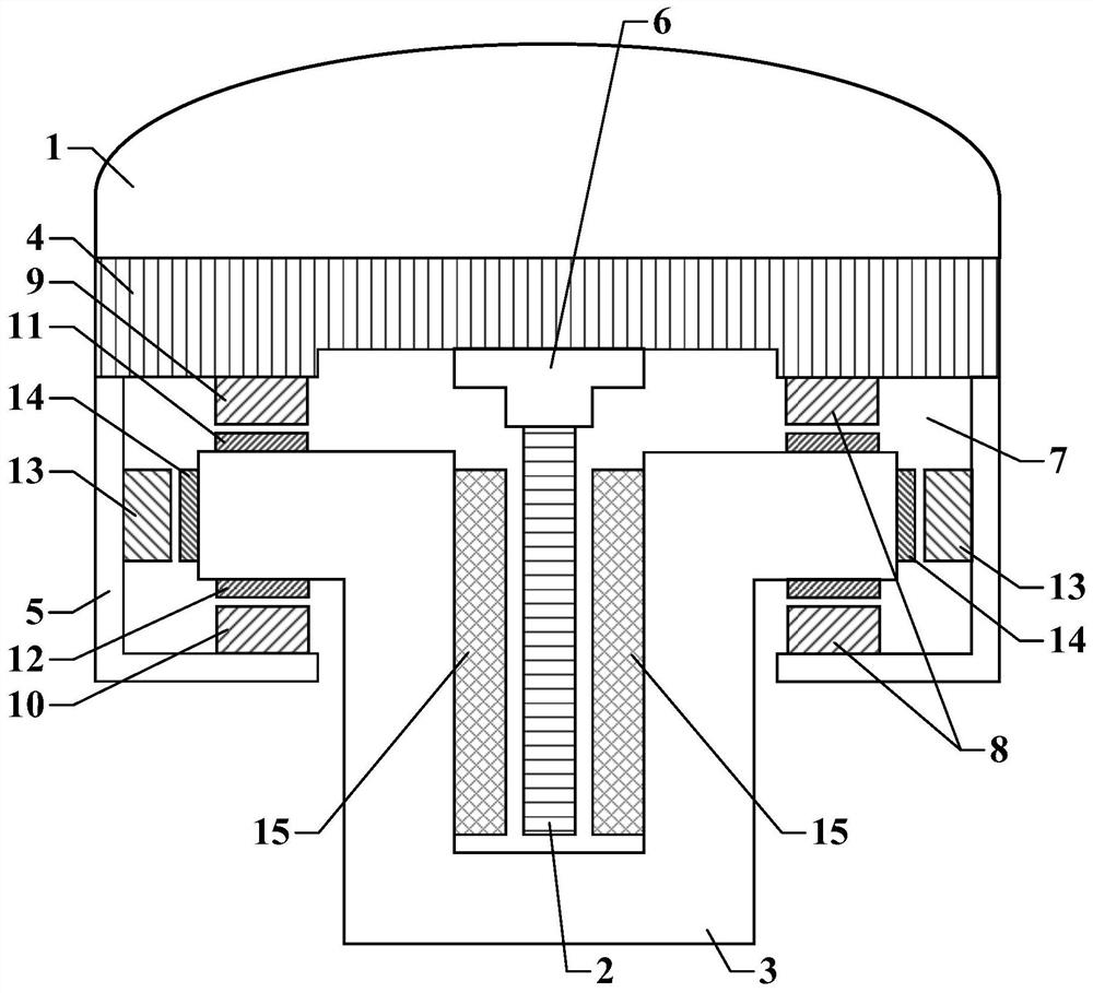
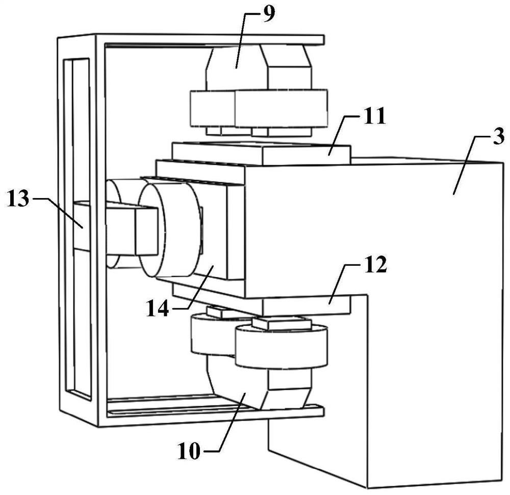
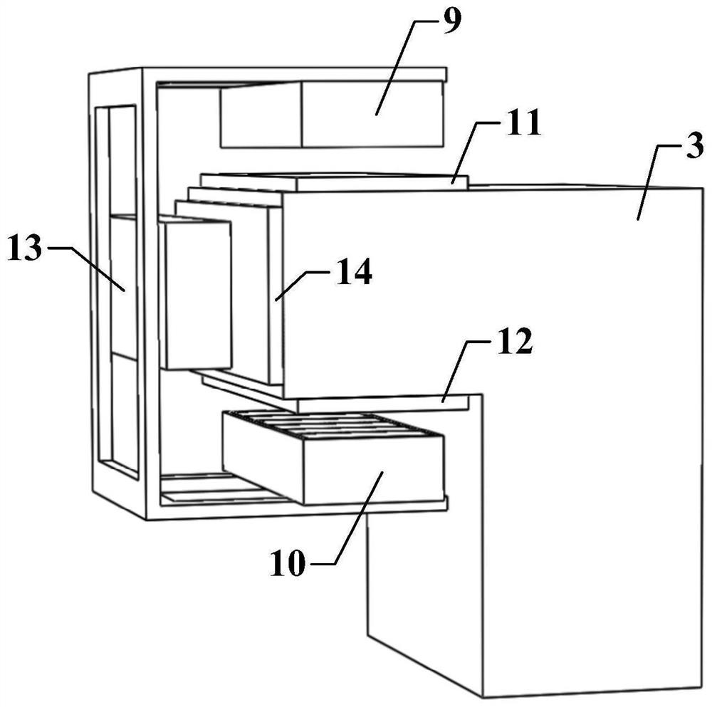
[0025]Such asfigure 1 The ultra-high-speed maglev test system using differential levitation guidance and double-sided linear motor is shown, including pneumatic streamline housing 1, supporting travel mechanism, differential levitation magnet, differential guide magnet, linear motor mover 2, linear motor double-sided Stator and track infrastructure 3; wherein the supporting walking mechanism includes an upper car body frame 4, two lower L-shaped support arms 5 and a mover fixing seat 6. Two lower L-shaped support arms 5 are symmetrically arranged on both sides of the lower surface of the upper car body frame 4, that is, the top of the vertical plate of one lower L-shaped support arm 5 is fixed on one side of the lower surface of the upper car body frame 4, and the other lower layer The top of the vertical plate of the L-shaped support arm 5 is fixed on the ...


PUM


Abstract

The invention discloses an ultra-high-speed magnetic levitation test system adopting differential levitation guide and a bilateral linear motor. The ultra-high-speed magnetic levitation test system comprises a pneumatic streamline shell, a supporting walking mechanism, a differential levitation magnet, a differential guide magnet, a levitation rail surface, a guide rail surface, a linear motor rotor, a linear motor bilateral stator and a rail infrastructure. The supporting walking mechanism comprises an upper-layer vehicle body frame, a lower-layer L-shaped supporting arm and a rotor fixing base. A sleeper part of the track infrastructure extends into a suspension cavity defined by the lower-layer L-shaped supporting arm and the upper-layer vehicle body frame, the differential type suspension magnet is vertically arranged in the suspension cavity, and the differential type guide magnet is transversely arranged in the suspension cavity. Structural switching of an electromagnetic attraction force and electric repulsion force two-type suspension guide scheme and an asynchronous induction and permanent magnet synchronous two-type linear motor mover scheme is realized, and full technical verification and performance comparison can be performed on the two-type suspension guide and linear motor schemes. And a theoretical basis and a test support are provided for research and development of an ultrahigh-speed magnetic levitation system and selection of related technical schemes.

Description

Technical field[0001]The invention belongs to the technical field of high-speed maglev and electromagnetic propulsion, and specifically relates to an ultra-high-speed maglev test system adopting a differential suspension guide and a bilateral linear motor.Background technique[0002]According to the levitation mechanism, the magnetic levitation system is mainly divided into electromagnetic levitation type (EMS: Electromagnetic Suspension) and electric levitation type (EDS: Electrodynamic Suspension). The two use electromagnetic suction and electric repulsion to achieve levitation; if they are divided into four types according to the operating speed : Low speed (≤100km / h), medium speed (100~350km / h), high speed (350~600km / h) and super high speed (≥600km / h). Compared with traditional contact mechanical supports such as wheel sets, sliders, bearings, etc., the magnetic levitation system adopts non-contact levitation support, which can effectively compensate for the inherent defects of me...

Claims


Application Information

Patent Timeline
Patent Type & Authority Applications(China)
IPC IPC(8): G01M17/08
CPCG01M17/08
Inventor 徐杰王东李冠醇晏明王星余翔徐敦煌
Owner NAVAL UNIV OF ENG PLA
Why Eureka
Try Eureka