Supercharge Your Innovation With Domain-Expert AI Agents!

Output circuit of driver

A technology of output circuit and drive device, applied in static memory, instrument, static indicator, etc., can solve the problem of image quality display efficiency decline and so on

Active Publication Date: 2021-01-19
NOVATEK MICROELECTRONICS CORP
View PDF15 Cites 0 Cited by
  • Summary
  • Abstract
  • Description
  • Claims
  • Application Information

AI Technical Summary

Problems solved by technology

However, existing power reduction techniques are usually accompanied by a decrease in image quality and / or display efficiency

Method used


Image

  • Output circuit of driver
  • Output circuit of driver
  • Output circuit of driver

Examples


Embodiment Construction

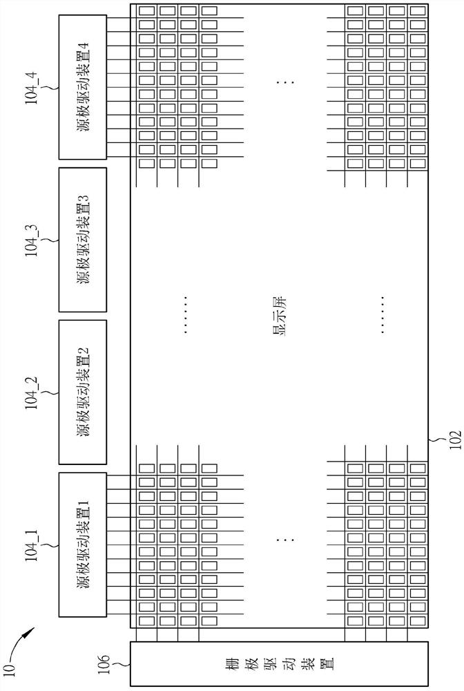
[0042] Please refer to figure 1 , figure 1 A schematic diagram of the general display system 10 is shown. The display system 10 includes a display screen 102 , at least one source driving device 104_1 - 104_4 and a gate driving device 106 . The display screen 102 includes an array of sub-pixels, wherein each sub-pixel can receive voltage data from a corresponding source driver according to a control signal from the gate driver 106 . In general, display system 10 may include any number of source drivers, depending on the size and resolution of the display screen, figure 1 The four source drivers 104_1 - 104_4 shown are just an example. In one embodiment, the gate driving device 106 can be disposed on the glass substrate of the display screen 102 to implement a gate-on-array (GOA) structure.

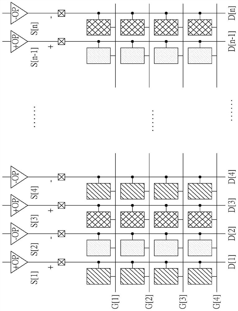
[0043] figure 2 A detailed structure of the display system 10 is shown. Wherein, each sub-pixel is connected to the gate driving device 106 through gate lines G[1], G[2], . . . ] c...


PUM


Abstract

The invention discloses an output circuit of a driver. The output circuit includes a plurality of output nodes, a first output buffer group and a multiplexer. The first output buffer group is configured to output data to the plurality of output nodes, wherein each output buffer in the first output buffer group is configured to output data to at least two output nodes among the plurality of outputnodes. The multiplexer, coupled between the plurality of output nodes and the first output buffer group, is configured to select to couple each output buffer in the first output buffer group to one ofthe plurality of output nodes.

Description

technical field [0001] The invention relates to an output circuit of a driving device, in particular to an output circuit applicable to a source driving device of a display screen. Background technique [0002] Liquid Crystal Display (LCD) has the advantages of thin and light appearance, low power consumption and low radiation, and has been widely used in computer screens, mobile phones, personal digital assistants (Personal Digital Assistant, PDA), flat-panel TVs and other communication / entertainment equipment and other electronic products. The principle of liquid crystal display is to change the rotation angle of liquid crystal molecules in the liquid crystal layer by changing the voltage difference between the two ends of the liquid crystal layer, and the light transmittance of the liquid crystal layer can be changed accordingly, which is further combined with the light source provided by the backlight module to display image. [0003] The liquid crystal display include...

Claims


Application Information

Patent Timeline
Patent Type & Authority Applications(China)
IPC IPC(8): G09G3/36
CPCG09G3/3688G09G2310/0291G09G2310/0297G09G3/3614G09G3/3685G09G2300/0426G09G2300/0408G09G2310/0221G09G2310/0218G09G2310/0213G09G2310/027G09G2310/04G09G2330/021G11C7/1057G09G2300/0456
Inventor 杨琇惠郑彦诚徐锦鸿
Owner NOVATEK MICROELECTRONICS CORP
Features
  • R&D
  • Intellectual Property
  • Life Sciences
  • Materials
  • Tech Scout
  • Unparalleled Data Quality
  • Higher Quality Content
  • 60% Fewer Hallucinations
Learn More