Flow regulation device utilizing flow coefficient of flow regulator

A technology of flow regulating device and flow regulator, which is applied in watering devices, applications, machines/engines, etc., can solve the problems of high maintenance cost and fixed nozzle flow rate, and achieve the effect of saving manufacturing costs and avoiding waste of water resources.

Inactive Publication Date: 2021-01-22
西安德厚电子科技有限公司
View PDF2 Cites 3 Cited by
  • Summary
  • Abstract
  • Description
  • Claims
  • Application Information

AI Technical Summary

Problems solved by technology

[0007] The purpose of the present invention is to solve the problem that the flow rate of the sprinkler head is fixed in the prior art. Once the lawn area is large, a sprinkler head needs to be installed and the maintenance cost is high. A flow adjustment method using the flow coefficient of the flow regulator is proposed device

Method used


Image

  • Flow regulation device utilizing flow coefficient of flow regulator
  • Flow regulation device utilizing flow coefficient of flow regulator
  • Flow regulation device utilizing flow coefficient of flow regulator

Examples


Embodiment 1

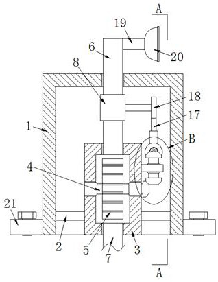
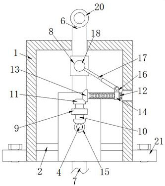
[0025] Example 1 as Figure 1-3 As shown, a flow regulating device using the flow coefficient of the flow regulator 8 includes a box body 1, the inside of the box body 1 is fixed with a hollow column 3 through a connecting rod 2, and the inside of the hollow column 3 rotates through two first bearings The first rotating rod 4 is provided, and the first bearing adopts a sealed bearing to prevent the hollow column 3 from leaking. The first water pipe 6 and the second water pipe 7 are fixedly sleeved, the pipe wall of the first water pipe 6 is fixedly provided with a flow regulator 8, the right end of the first rotating rod 4 penetrates to the outside of the hollow column 3 and is fixedly connected with a first The bevel gear 15, the first bevel gear 15 is fixedly connected with a driving mechanism and an adjusting mechanism through a transmission mechanism.

Embodiment 2

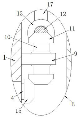
[0026] Embodiment 2 is on the basis of embodiment 1 such as Figure 2-3 As shown, the transmission mechanism includes a fixed block 9, a second rotating rod 10 and a second bevel gear 11. The fixed block 9 is fixedly arranged on the right side wall of the hollow column 3 and passes through the second bearing and the rod wall of the second rotating rod 10. Rotationally connected, two second bevel gears 11 are provided and are respectively fixedly arranged at both ends of the second rotating rod 10 , and the second bevel gear 11 on the lower side is engaged with the first bevel gear 15 .

Embodiment 3

[0027] Embodiment 3 is such as on the basis of embodiment 1 Figure 2-3 As shown, the drive mechanism includes a reciprocating screw 12, a third bevel gear 13 and a reciprocating slider 14. The right end rod wall of the reciprocating screw 12 is rotatably connected with the inner wall of the box body 1 through a third bearing, and the left end is rotatably connected with the inner wall of the box body 1 through a third bevel gear. 13 is engaged with the second bevel gear 11 on the upper side.


PUM


Abstract

The invention relates to the technical field of flow regulation, and discloses a flow regulation device utilizing the flow coefficient of a flow regulator. The flow regulation device comprises a box body, a hollow column is fixedly arranged in the box body through a connecting rod, a first rotating rod is rotatably arranged in the hollow column through two first bearings, and an impeller is fixedly arranged on the rod wall of the first rotating rod; through holes are formed in the upper surface and the lower surface of the hollow column, a first water pipe and a second water pipe are fixedly connected to the upper surface and the lower surface of the hollow column in a sleeved manner correspondingly, a flow regulator is fixedly arranged on the pipe wall of the first water pipe, and the right end of the first rotating rod penetrates out of the hollow column and is fixedly connected with a first bevel gear; and the first bevel gear is fixedly connected with a driving mechanism and an adjusting mechanism through a transmission mechanism. According to the flow regulation device, the flow can be automatically adjusted, and the irrigation effect is improved.

Description

technical field [0001] The invention relates to the technical field of flow regulation, in particular to a flow regulating device utilizing the flow coefficient of a flow regulator. Background technique [0002] The flow regulator has an annular throttle body made of elastic material, which delimits between itself and the regulating star wheel a control gap that varies under the pressure of the fluid flowing through, wherein the regulating star wheel held on the lead screw is in its The outer circumference is provided with a longitudinally varying adjustment profile and is guided displaceably in the longitudinal direction, so that the rotational movement of the spindle can be converted into a longitudinal movement of the adjustment star wheel so that by adjusting the relative position of the star wheel and the throttle body Change to change the control gap. [0003] Wherein the patent No. CN108934990A discloses a garden lawn irrigation device, including a base, the upper su...

Claims


Application Information

Patent Timeline
Patent Type & Authority Applications(China)
IPC IPC(8): A01G25/02A01G25/16F03B13/00
CPCA01G25/02A01G25/16F03B13/00
Inventor 李军荣
Owner 西安德厚电子科技有限公司
Why Eureka
Try Eureka