Cleaning machine and cleaning method
A cleaning machine and motor shaft technology, applied in the field of cleaning machines, can solve the problems of residue stuck, troublesome, difficult to discharge to the slag collection basket, etc., to achieve the effect of improving slag collection and avoiding accumulation
- Summary
- Abstract
- Description
- Claims
- Application Information
AI Technical Summary
Problems solved by technology
Method used
Image

Examples
Embodiment Construction
[0026] The present invention will be further described in detail below in conjunction with the accompanying drawings and embodiments.
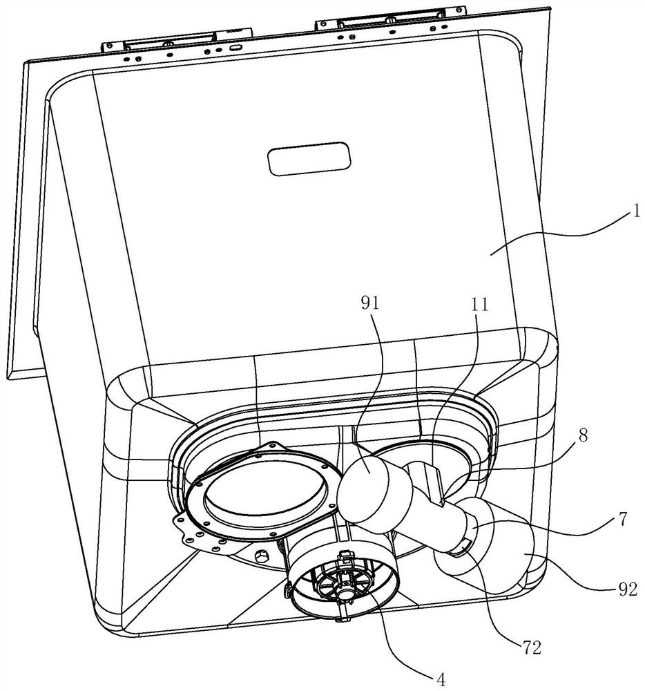
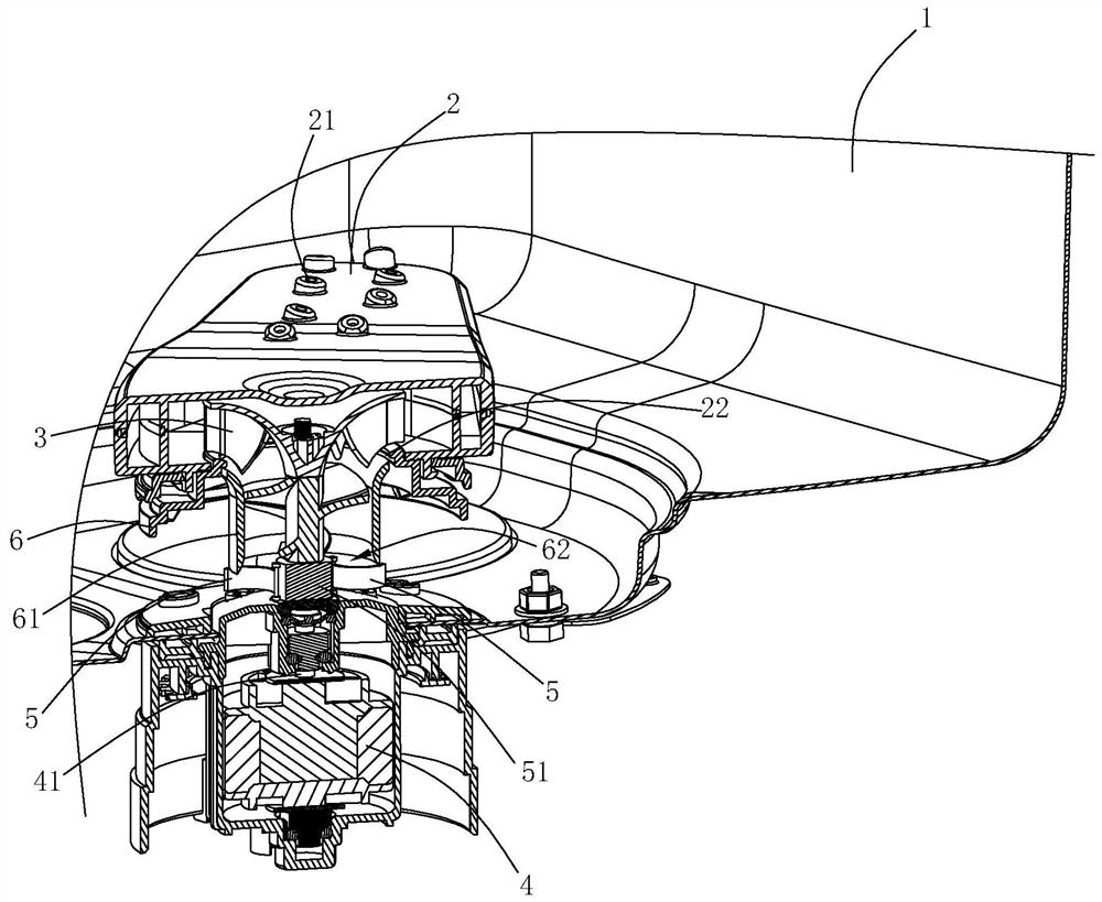
[0027] Such as Figure 1~6 As shown, the washing machine of the present embodiment includes a casing 1, a spray arm 2, a water-drawing impeller 3 and a motor 4, the spray arm 2 is arranged in the casing 1 and has a water inlet 21 on the bottom wall, and a water inlet 21 on the top wall. The water spray hole 22, the water drawing impeller 3 is rotatably arranged in the box body 1 and is used to pump the water at the bottom of the box body 1 to the spray arm 2, and the motor 4 is arranged at the bottom of the box body 1 and is used to drive the water drawing impeller 3 rotate.
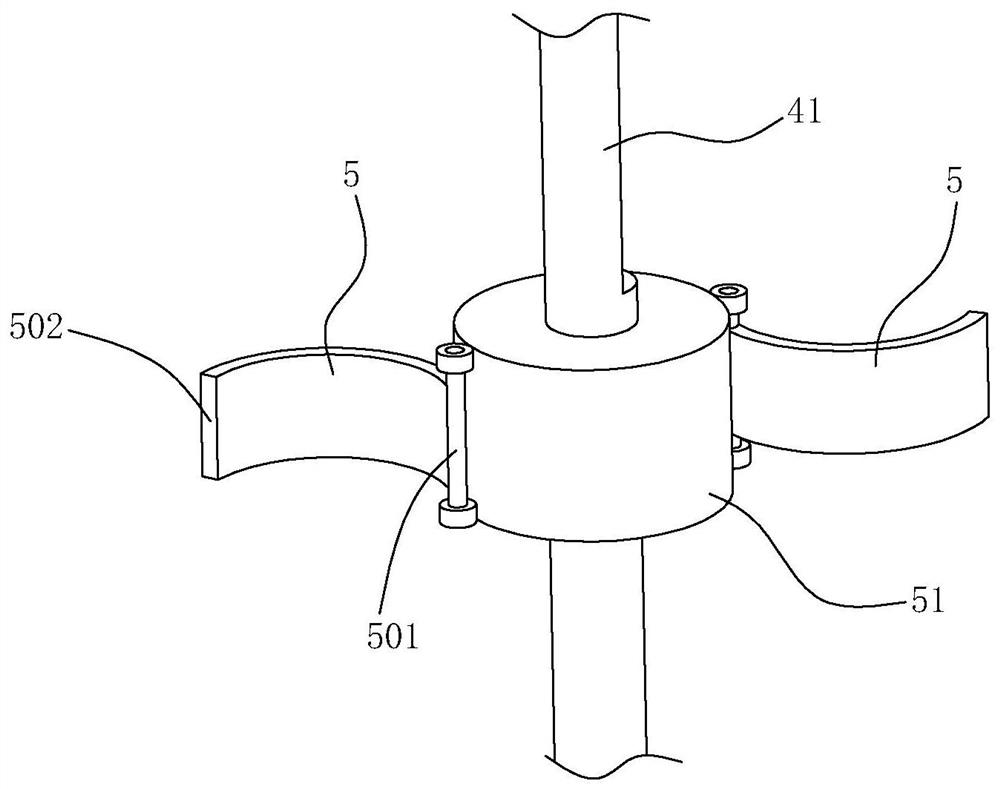
[0028] The above-mentioned motor 4 has a motor shaft 41 capable of forward and reverse rotation. The motor shaft 41 vertically passes through the bottom wall of the box body 1 and is connected to the water-drawing impeller 3. On the outer peripheral wall of the shaft 4...
PUM
 Abstract
Description
Claims
Application Information
 - Generate Ideas
- Intellectual Property
- Life Sciences
- Materials
- Tech Scout
- Unparalleled Data Quality
- Higher Quality Content
- 60% Fewer Hallucinations
Browse by: Latest US Patents, China's latest patents, Technical Efficacy Thesaurus, Application Domain, Technology Topic, Popular Technical Reports.
© 2025 PatSnap. All rights reserved.Legal|Privacy policy|Modern Slavery Act Transparency Statement|Sitemap|About US| Contact US: help@patsnap.com