Batch marking equipment for triangular marks of oil casing screwed joints

A technology for threaded joints and oil casings, applied in printing, typewriters, etc., can solve the problems of time-consuming cost, affecting marking quality, and prone to misalignment, reducing labor and time costs, improving marking quality, and reducing misalignment. effect of risk

Active Publication Date: 2021-01-22
熊勇
View PDF12 Cites 1 Cited by
  • Summary
  • Abstract
  • Description
  • Claims
  • Application Information

AI Technical Summary

Problems solved by technology

This type of existing technology has the following defects: (1) marking the casing one by one is inefficient and time-consuming and labor-intensive; (2) since only a single casing can be hammer-marked at a time, the The printing tool and the casing are completely stabilized by manpower, which is prone to misalignment and affects the marking quality; (3) The marking process relies on manual hammering, which consumes a lot of energy

Method used


Image

  • Batch marking equipment for triangular marks of oil casing screwed joints
  • Batch marking equipment for triangular marks of oil casing screwed joints
  • Batch marking equipment for triangular marks of oil casing screwed joints

Examples


Embodiment 1

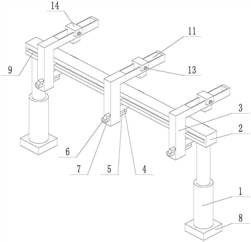
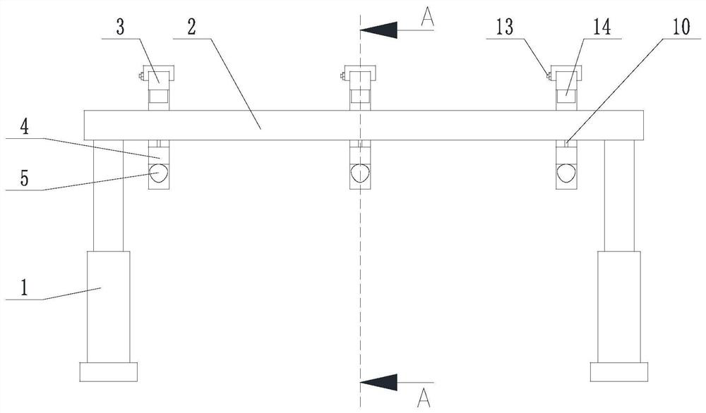
[0048] Such as Figure 1 to Figure 4 The shown oil casing threaded joint triangular mark batch marking equipment includes two support legs 1, a cross bar 2 fixed between the two support legs 1, and a plurality of L-shaped pieces 3 are connected to the cross bar 2. One end of the L-shaped piece 3 is slidingly fitted with the side of the crossbar 2, and the other end is located above the crossbar 2 and straddles the crossbar 2. The L-shaped piece 3 can slide along the axis of the crossbar 2; it also includes a sliding fit on the L-shaped piece 3 on the clamping piece 4, the clamping piece 4 can slide in the longitudinal direction, the clamping piece 4 is located below the cross bar 2 and crosses the cross bar 2, a cam 5 is arranged under the clamping piece 4, and the cam 5 is formed by The drive mechanism is driven to rotate; the end of the L-shaped piece 3 above the cross bar 2 is also provided with a marking assembly. The driving mechanism includes a rotating shaft 6 fixedly ...

Embodiment 2

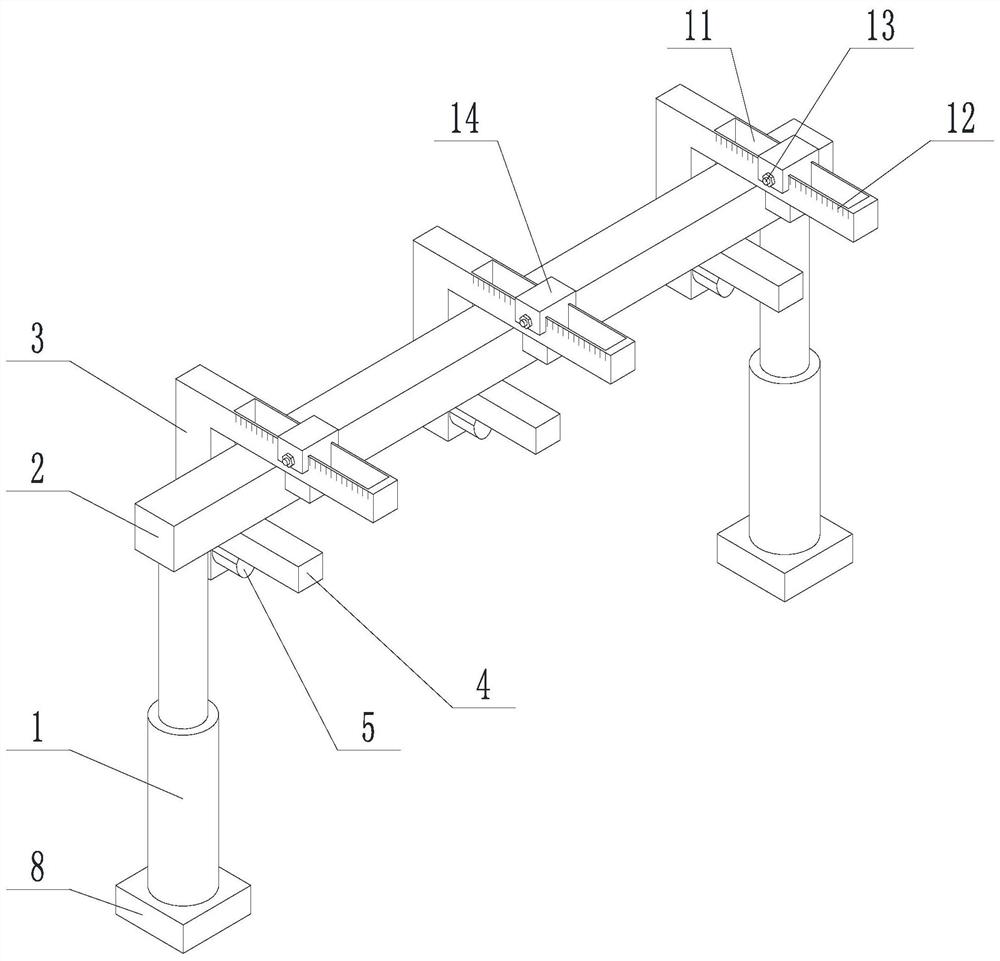
[0051] Such as Figure 1 to Figure 6 In the shown oil casing threaded joint triangular mark batch marking equipment, on the basis of Embodiment 1, the end of the L-shaped piece 3 above the cross bar 2 is provided with a through groove 11 communicating up and down, and the through groove 11 The long axis is perpendicular to the axis of the cross bar 2 , and the marking assembly can slide along the slot 11 . A scale 12 is provided on the outer wall of the through groove 11 ; and a set bolt 13 for locking the marking assembly on the through groove 11 is also included. The marking assembly includes a slider 14 slidably connected to the through groove 11, a housing cavity 15 is provided at the bottom of the slider 14, and a stamping block 16 is slidably fitted in the housing cavity 15, and a die 17 is arranged at the bottom of the stamping block 16. A threaded blind hole 18 is provided on the top of the stamping block 16; a screw rod 19 matching the threaded blind hole 18 is also ...


PUM


Abstract

The invention discloses batch marking equipment for triangular marks of oil casing pipe screwed joints. The equipment comprises two supporting legs and a transverse rod fixed between the two supporting legs; a plurality of L-shaped pieces are connected onto the transverse rod; one end of each L-shaped piece is in sliding fit with the side surface of the transverse rod, the other end is located above the transverse rod and strides over the transverse rod; the L-shaped pieces can slide along the axis of the transverse rod; the equipment further comprises clamping pieces in sliding fit with the L-shaped pieces; the clamping pieces can slide in the longitudinal direction; the clamping pieces are located below the transverse rod and stride across the transverse rod; cams are arranged below theclamping pieces; the cams are driven by a driving mechanism to rotate; the end, located above the transverse rod, of each L-shaped piece is further provided with a marking assembly. According to the batch marking equipment for the triangular marks of the oil casing pipe screwed joints, the technical problem of low efficiency due to the fact that casing pipes are required to be marked one by one inthe prior art is solved, and the purpose that the triangular marks are printed on a row of laid casing pipes in batches at the same time is achieved.

Description

technical field [0001] The invention relates to the field of petroleum casing pipes, in particular to a batch printing device for triangular marks of threaded joints of petroleum casing pipes. Background technique [0002] Oil casing is a steel pipe used to support the walls of oil and gas wells to ensure the normal operation of the entire oil well after the drilling process and completion. important components. Each well generally uses several layers of casing according to different drilling depths and geological conditions. Cement cementing is used after the casing is lowered into the well, and the drilling project can only be regarded as a temporary conclusion after the cementing is completed. [0003] Two adjacent bushings are connected by threaded joints, and the connection is the weak point of the whole bushing string. API SPEC 5B "Processing, Measurement and Inspection of Tubing, Casing and Line Pipe Threads" stipulates that for the partial trapezoidal thread and l...

Claims


Application Information

Patent Timeline
Patent Type & Authority Applications(China)
IPC IPC(8): B41J3/407B41J3/413
CPCB41J3/4073B41J3/413
Inventor 不公告发明人
Owner 熊勇
Why Eureka
Try Eureka