Burner-containing auger sludge sealing, drying and incinerating equipment for feeding materials from outer kettle to inner kettle

A technology for incinerating sludge and burners, which is applied in dehydration/drying/concentrated sludge treatment, combustion methods, combustion types, etc. Decomposition incineration, avoid discharge, fully absorb heat and dry the effect

Pending Publication Date: 2021-01-22
湖南奔骥环保能源科技有限责任公司
View PDF0 Cites 0 Cited by
  • Summary
  • Abstract
  • Description
  • Claims
  • Application Information

AI Technical Summary

Problems solved by technology

The existing double-kettle drying pyrolysis incineration equipment is equipped with inner and outer kettles, and a burner is installed on the sealing sleeve at the other end of the double-kettle equipment to directly enter the inner and outer kettles to dry the sludge. The two ends between the kettle and the outer kettle are connected to each other. At this time, the heat of the burner is directly discharged from one end to the other. The heat is not recycled, that is, there is no advantage of energy saving; and because the sludge enters from the inner kettle, the inner The sludge entering the kettle has a high moisture content and is difficult to be incinerated at high temperature. However, when it is dried, part of the sludge will be burnt and produce an unpleasant odor. Because the high temperature environment cannot be formed in the inner kettle, the odor cannot be ablated, causing environmental pollution. Pollution
In addition, due to the high moisture content of the sludge, it is easy to clump during operation and it is difficult to quickly absorb heat and dry

Method used


Image

  • Burner-containing auger sludge sealing, drying and incinerating equipment for feeding materials from outer kettle to inner kettle
  • Burner-containing auger sludge sealing, drying and incinerating equipment for feeding materials from outer kettle to inner kettle

Examples


Embodiment Construction

[0015] The following will clearly and completely describe the technical solutions in the embodiments of the present invention with reference to the accompanying drawings in the embodiments of the present invention. Obviously, the described embodiments are only some, not all, embodiments of the present invention. Based on the embodiments of the present invention, all other embodiments obtained by persons of ordinary skill in the art without making creative efforts belong to the protection scope of the present invention.

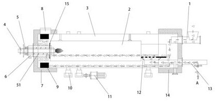
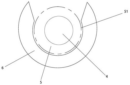
[0016] see figure 1 , the present invention provides a technical solution: the outer kettle is used to feed the inner kettle with an auger containing a burner to seal and dry the sludge incineration equipment, mainly including the outer kettle 3, the inner kettle 2 and the feeder 1; the inner kettle 2 is fixed on the outer kettle 3 The inside rotates together with the outer kettle 3, the feeder 1 is connected to one end of the outer kettle 3, and the side of t...


PUM


Abstract

The invention discloses burner-containing auger sludge sealing, drying and incinerating equipment for feeding materials from an outer kettle to an inner kettle, which comprises an outer kettle, an inner kettle assembled in the outer kettle and rotating along with the outer kettle, and a feeder connected with the outer kettle, the burner-containing auger for transferring materials is arranged in the center of the side, away from the feeder, of the outer kettle, and a hollow shaft is arranged in the burner-containing auger; a pipeline for fixing the burner is arranged in the hollow shaft; sludgeis conveyed to the outer kettle through the feeder to be dried, and the dried sludge is extruded and densely conveyed to the inner kettle through the auger with the burner to be pyrolyzed and incinerated. The sludge is extruded and compacted by the burner-containing auger and then is conveyed from the outer kettle to the inner kettle, so that only one end of the feeder of the inner kettle and theouter kettle is communicated with gas, the temperature generated by the burner can only be circulated along the sludge running direction, and the heat generated by energy consumption is fully utilized; meanwhile, the outer kettle is firstly dried and then the inner kettle is subjected to high-temperature pyrolysis incineration, so that harmful gas can be ablated in the inner kettle, and peculiarsmell gas is prevented from being discharged into the atmosphere.

Description

technical field [0001] The invention relates to the technical field of pyrolysis equipment, in particular to an auger containing a burner used for feeding materials from an outer kettle to an inner kettle to seal and dry incineration sludge. Background technique [0002] At present, the rapid development of society has caused human beings to produce too much domestic and industrial sludge, which has caused environmental pollution. Therefore, in order to protect the environment, people began to design new equipment that can dry and pyrolyze sludge. The existing double-kettle drying pyrolysis incineration equipment is equipped with inner and outer kettles, and a burner is installed on the sealing sleeve at the other end of the double-kettle equipment to directly enter the inner and outer kettles to dry the sludge. The two ends between the kettle and the outer kettle are connected to each other. At this time, the heat of the burner is directly discharged from one end to the ot...

Claims


Application Information

Patent Timeline
Patent Type & Authority Applications(China)
IPC IPC(8): C02F11/10C02F11/13F23G7/00
CPCC02F11/10C02F11/13F23G7/001
Inventor 李艺肖国华江钰欧阳李黎
Owner 湖南奔骥环保能源科技有限责任公司
Why Eureka
Try Eureka