A building foundation construction device

A technology for construction devices and foundations, which is applied in construction, infrastructure engineering, separation methods, etc., can solve problems such as affecting work progress, increasing construction costs, and long construction periods, so as to improve dust removal effects, improve work efficiency, and reduce construction costs. cost effect

Inactive Publication Date: 2022-04-29
鹤山市伟创工程有限公司
View PDF0 Cites 0 Cited by
  • Summary
  • Abstract
  • Description
  • Claims
  • Application Information

AI Technical Summary

Problems solved by technology

[0003] 1. In the process of forming multiple holes in the existing foundation piles, the drilling tools with fixed apertures are used, and the distance between adjacent foundation piles cannot be adjusted. When it is necessary to form foundation piles with relatively large distances When the corresponding drilling tool must be replaced, the construction cost is increased, and the construction period is longer, which affects the work progress
[0004] 2. During the hole forming process of the existing foundation pile drilling device, the hole forming speed in the soft soil foundation is faster, but when pouring concrete, the drilling tool needs to be removed, and then the concrete is poured into the formed In the inner cavity of the soil hole, due to the aging problem, the soft soil is easy to collapse, resulting in the need for secondary drilling, which reduces the work efficiency and increases the cost
[0005] 3. The existing foundation pile drilling device is easy to cause dust flying during the hole forming process, and the existing drilling device is not equipped with a corresponding dust removal device, which causes the environment on the construction site to be chaotic and affects the personal safety of the staff. Reduced foundation construction site safety

Method used


Image

  • A building foundation construction device
  • A building foundation construction device
  • A building foundation construction device

Examples


Embodiment Construction

[0030] The following will clearly and completely describe the technical solutions in the embodiments of the present invention with reference to the accompanying drawings in the embodiments of the present invention. Obviously, the described embodiments are only some, not all, embodiments of the present invention. Based on the embodiments of the present invention, all other embodiments obtained by persons of ordinary skill in the art without making creative efforts belong to the protection scope of the present invention.

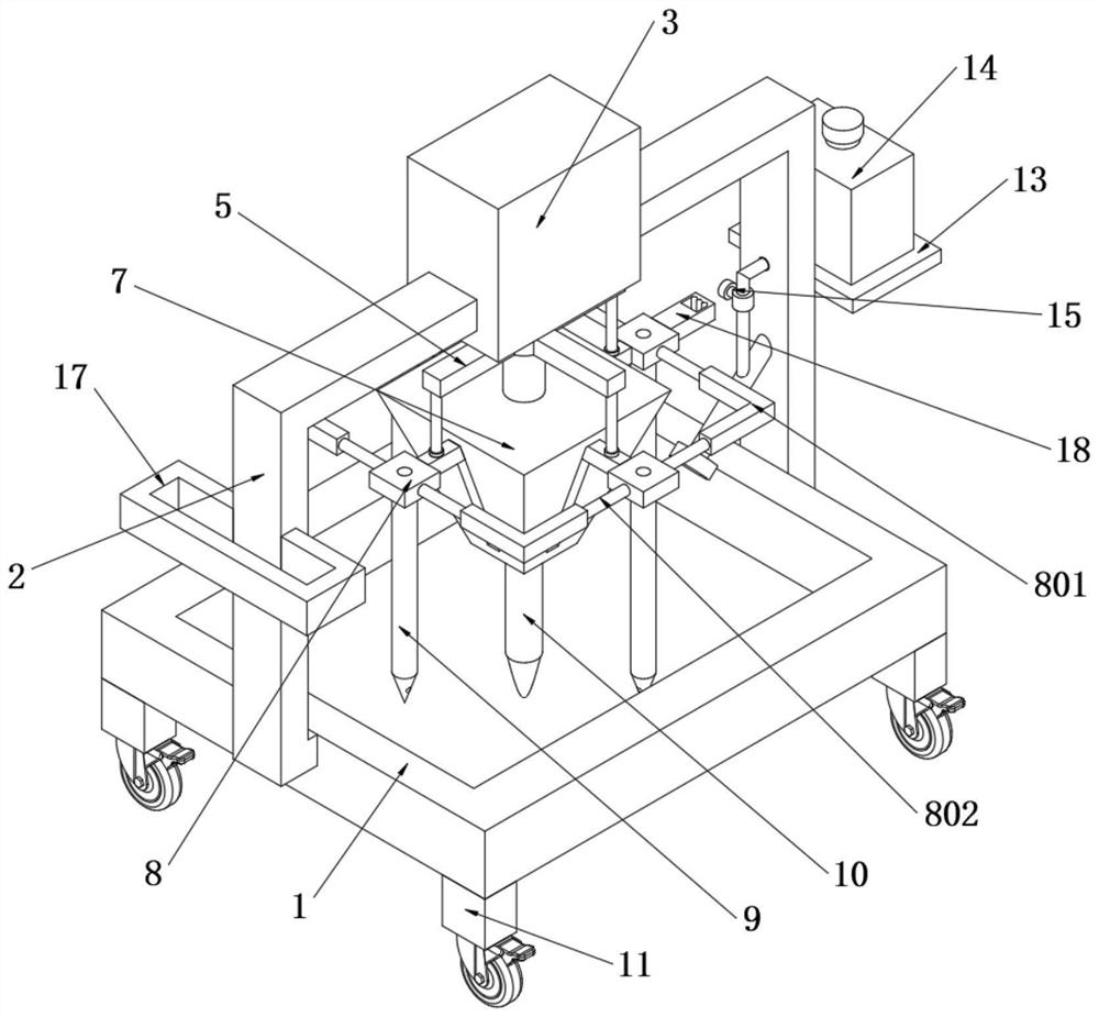
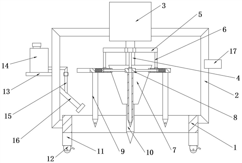
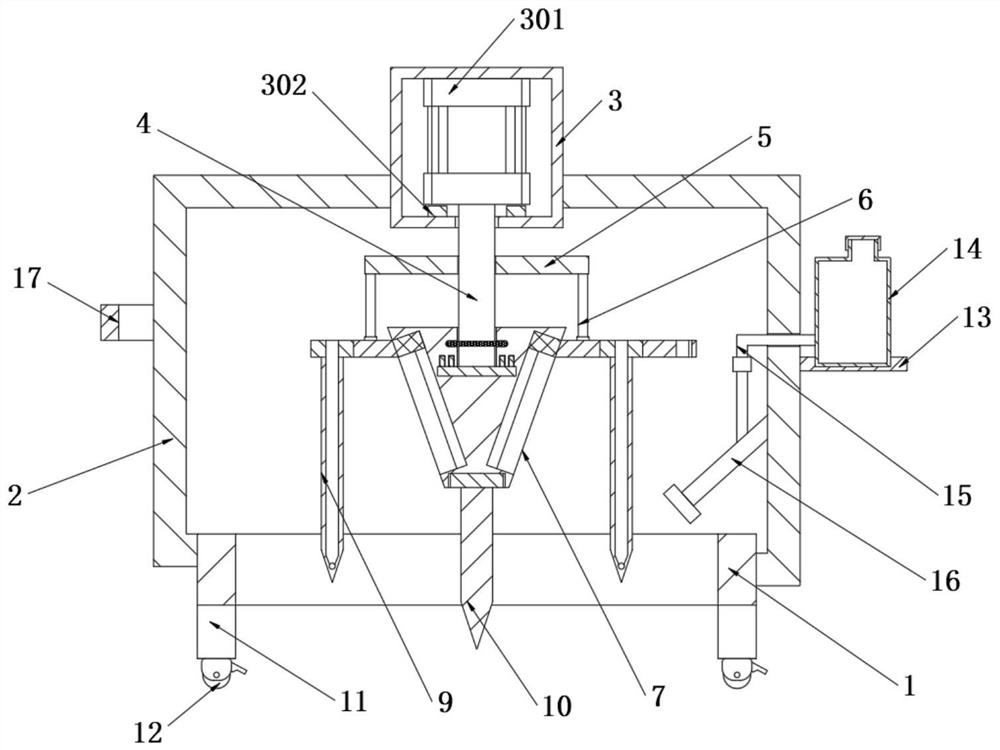
[0031] The present invention provides such as Figure 1-7 A building foundation construction device shown includes a base plate 1, and supports 2 are fixedly connected to both sides of the base plate 1. The cross section of the support 2 is C-shaped, which is convenient for the fixed connection of the storage box 3. The middle part of the support 2 is provided with a hydraulic Rod 4, the bottom of hydraulic rod 4 is fixedly interspersed to be connected with fi...


PUM


Abstract

The invention discloses a building foundation construction device, which comprises a base plate, supports are fixedly connected to both sides of the base plate, a hydraulic rod is arranged on the support, a fixing seat is arranged at the bottom of the hydraulic rod, and slide grooves are provided on the sides of the fixing seat , the inner cavity of the chute is provided with a slider, one side of the slider is provided with a bearing plate, the bottom of the bearing plate is provided with a first perforated pile, one side of the two bearing plates is provided with a slide bar, and two A bending rod is arranged between the sliding rods, a spring is arranged on one side inner wall of the sliding chamber of the bending rod, an extruding block is arranged on the spring, and a second perforated pile is arranged at the bottom of the fixing seat. The present invention utilizes the cooperation of the fixing seat, the chute, the sliding block, the connecting rod and the bearing plate to facilitate the control of the relative distance between the four first perforated piles, and utilizes the cooperation of the sliding rod, the bending rod, the spring and the extruding block , to facilitate the synchronous sliding of the four first perforated piles, improve the accuracy of the spacing, and use the cooperation of the second perforated piles and the fixing seat to socket the second perforated piles with different apertures.

Description

technical field [0001] The invention relates to the field of construction devices, in particular to a building foundation construction device. Background technique [0002] In my country's current building foundation treatment methods, pile foundation construction is required. Pile foundation construction is a deep foundation composed of piles and pile cap piles connected to the top of the pile or a single pile foundation connected by columns and pile foundations, referred to as pile foundation. According to the force characteristics, it can be divided into friction piles and end-bearing piles. According to the construction method, it can be divided into prefabricated piles and cast-in-place piles. The cast-in-place piles need to be drilled and poured with concrete to make concrete foundation piles. Existing The foundation pile drilling device mainly has the following disadvantages in use: [0003] 1. In the process of forming multiple holes in the existing foundation piles, ...

Claims


Application Information

Patent Timeline
Patent Type & Authority Patents(China)
IPC IPC(8): E02D7/06E02D7/14E02D7/16B01D47/06
CPCE02D7/06E02D7/14E02D7/16B01D47/06
Inventor 赵燕虎陈颖颖
Owner 鹤山市伟创工程有限公司
Why Eureka
Try Eureka