Supercharge Your Innovation With Domain-Expert AI Agents!

Bucket for excavator and using method

A technology for excavators and buckets, applied in the field of excavator accessories, can solve problems such as large gaps and poor bucket space utilization, and achieve the effects of reducing the difficulty of cleaning, improving utilization, and reducing gaps

Inactive Publication Date: 2021-01-22
湖南德力重工科技股份有限公司
View PDF6 Cites 0 Cited by
  • Summary
  • Abstract
  • Description
  • Claims
  • Application Information

AI Technical Summary

Problems solved by technology

[0003] The object of the present invention is to provide a bucket for an excavator and its use method, so as to solve the existing problems: after the existing bucket excavates the soil, the gap inside the bucket is large, and the space utilization rate of the bucket is poor

Method used


Image

  • Bucket for excavator and using method
  • Bucket for excavator and using method
  • Bucket for excavator and using method

Examples


Embodiment 1

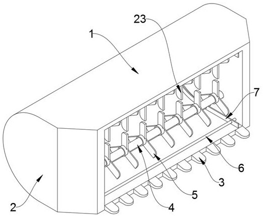
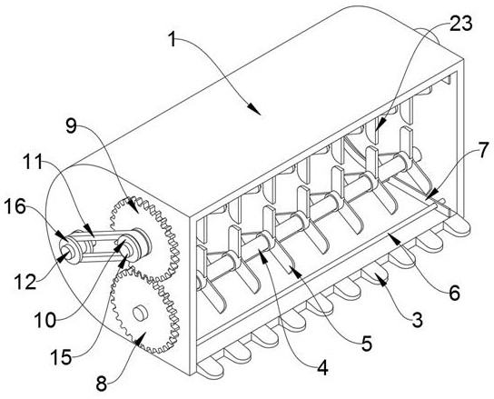
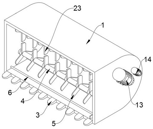
[0036] see Figure 1-7 As shown, the present invention is a bucket for an excavator, including a mechanical excavating bucket body 1, and a straight cavity and a semicircular cavity are opened inside the mechanical excavating bucket body 1, and the straight cavity is located in the mechanical excavating bucket body. The front end of the interior of 1 has a rectangular cross section. The semicircular cavity is located at the rear end of the mechanical excavation bucket body 1, and its cross section is semicircular. A plurality of third pulverizing knives 23 are clamped on the outside of the transmission shaft 15, a first rotating shaft 4 is rotatably connected to the lower end inside the flat cavity, and a plurality of first pulverizing knives 5 are clamped on the outside of the first rotating shaft 4, and The cutting direction of the first pulverizing tool 5 and the cutting direction of the third pulverizing tool 23 are in the opposite direction, the inside of the semicircular...

Embodiment 2

[0046] A method for using a bucket of an excavator is disclosed on the basis of Embodiment 1, the steps of which are as follows:

[0047] The first step: when in use, assemble the device on the arm of the excavator, and then use the excavator control device to excavate the soil, and the soil blocks will be dug into the interior of the mechanical excavator body 1 during excavation;

[0048] Second step: start the first motor 13 in the process of digging, and the first driven bevel gear 18 will be driven to rotate after the first motor 13 is started, because the first driven bevel gear 18 and the first driving bevel gear 19 pass through Mesh connection, when the first driven bevel gear 18 rotates, it will drive the first driving bevel gear 19 to rotate, and when the first driving bevel gear 19 rotates, it will drive the second rotating shaft 12 to rotate together, and when the second rotating shaft 12 rotates, it will Drive the second crushing tool 17 to crush the soil clods ins...


PUM


Abstract

The invention discloses a bucket for an excavator and a using method, and relates to the technical field of excavator accessories. The bucket comprises a mechanical soil digging bucket body; a straight cavity and a semicircular cavity are formed in the mechanical soil digging bucket body; the straight cavity is located at the front end in the mechanical soil digging bucket body; and the semicircular cavity is located at the rear end in the mechanical soil digging bucket body. A first motor is started to drive a first crushing cutter and a third crushing cutter to rotate in opposite directions,so that crushed soil is poured into the semicircular cavity while soil blocks are crushed; meanwhile, a second crushing cutter is driven to crush the soil blocks in the semicircular cavity, so that gaps between the soil blocks are effectively reduced, and the space utilization rate of the device can be greatly increased; and a second motor is started to drive a soil scraping plate to slide in thedirection of a circular positioning rod, and the soil scraping plate can clean the inner wall of the mechanical earth digging bucket body when sliding, so that the cleaning difficulty of the inner wall of the mechanical earth digging bucket body is greatly reduced.

Description

technical field [0001] The invention belongs to the technical field of excavator accessories, in particular to a bucket used for an excavator and a use method thereof. Background technique [0002] Excavator, also known as excavator, also known as excavator, is an earthmoving machine that uses a bucket to dig materials higher or lower than the bearing surface, and loads them into transport vehicles or unloads them to the stockyard. The materials excavated by excavators Mainly soil, coal, silt, and pre-loose soil and rock. Judging from the development of construction machinery in recent years, the development of excavators is relatively fast. Excavators have become one of the most important construction machinery in engineering construction. First, the bucket refers to the bucket used on the excavator, but the gap inside the bucket is large after the existing bucket is excavated, the space utilization rate of the bucket is poor, and it is difficult to clean the inside of the ...

Claims


Application Information

Patent Timeline
Patent Type & Authority Applications(China)
IPC IPC(8): E02F5/30E02F3/40
CPCE02F3/40E02F5/30
Inventor 胡承桓胡超
Owner 湖南德力重工科技股份有限公司
Features
  • R&D
  • Intellectual Property
  • Life Sciences
  • Materials
  • Tech Scout
  • Unparalleled Data Quality
  • Higher Quality Content
  • 60% Fewer Hallucinations
Learn More