Movable concrete mechanical vibrating device

A technology of concrete machinery and vibrating device, which is applied in construction, building structure, processing of building materials, etc., can solve the problems of low vibrating efficiency, increase the labor burden of staff, etc., and achieve high vibrating efficiency, saving manpower, The effect of increasing the vibrating area

Inactive Publication Date: 2021-01-22
曾祥瑞
View PDF6 Cites 3 Cited by
  • Summary
  • Abstract
  • Description
  • Claims
  • Application Information

AI Technical Summary

Problems solved by technology

[0004] However, in the actual use process, the above-mentioned device needs to be vibrated manually, and the vibrating efficiency is low. The staff need to continuously push the device with the mold table, which further increases the labor burden of the staff.

Method used


Image

  • Movable concrete mechanical vibrating device
  • Movable concrete mechanical vibrating device
  • Movable concrete mechanical vibrating device

Examples


Embodiment 1

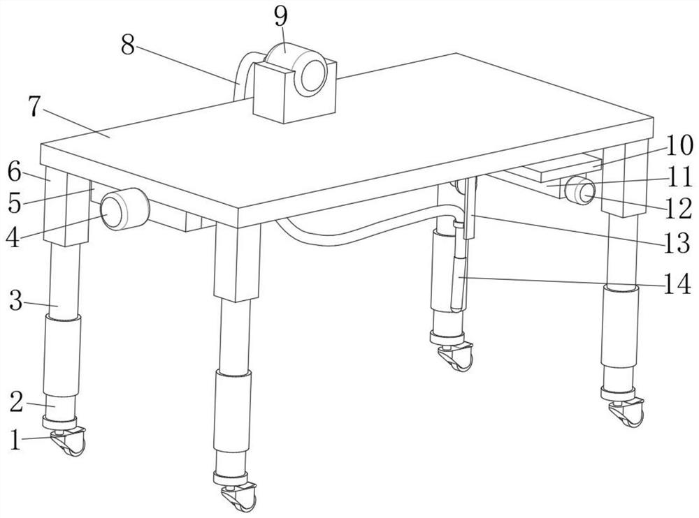
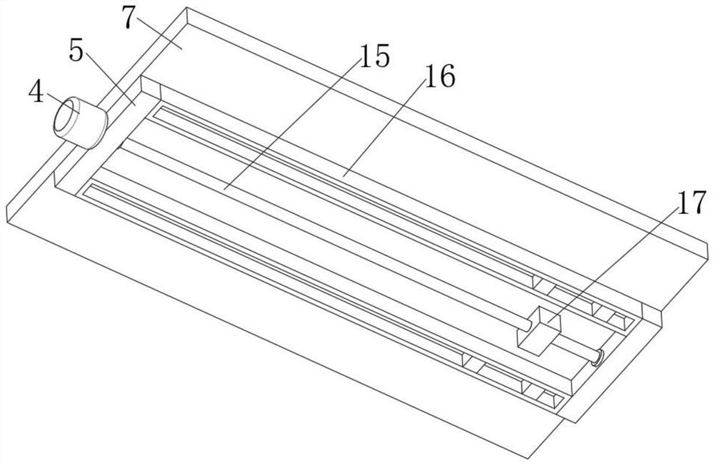
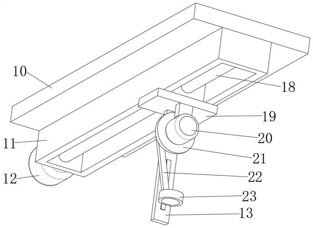
[0025] refer to Figure 1-4 , a mobile concrete mechanical vibration device, including a top plate 7, two symmetrically distributed first installation blocks 16 are fixed on the bottom outer wall of the top plate 7 by screws, and the bottom outer wall of the first installation block 16 has a first rectangular groove , the inner walls of the left and right sides of the first rectangular groove are fixed with the first sliding rail by screws, and the inner wall of the first sliding rail is slidably connected with the slider, and the outer wall of the bottom of the slider is fixed with the first movable plate 10 by screws, and the first The top outer wall of the movable plate 10 is fixed with the first movable block 17 by screws, the front side outer wall of the first installation block 16 is fixed with the mounting plate 5 by screws, and the front side outer wall of the mounting plate 5 is fixed with the first motor 4 by screws, The output shaft of the first motor 4 is fixedly c...

Embodiment 2

[0034] refer to Figure 4 , a mobile concrete mechanical vibrating device. Compared with Embodiment 1, this embodiment also includes a connecting plate 25 fixed on the peripheral outer wall of the mounting column 2 by screws, and the top outer wall of the connecting plate 25 is provided with threaded holes. The inner wall of the hole is threadedly connected with a third threaded rod 24 , and the bottom outer wall of the third threaded rod 24 is fixed with a support foot 26 .

[0035] When the device is in use, the third threaded rod 24 is rotated so that the supporting feet 26 touch the ground to support and fix the device, which is conducive to the stable operation of the vibrating concrete work.


PUM


Abstract

The invention belongs to the technical field of concrete vibration, and particularly relates to a movable concrete mechanical vibrating device. Aiming at the problems that when concrete is vibrated, adevice needs to be continuously pushed manually to move, and manpower is consumed, the following scheme is proposed, the movable concrete mechanical vibrating device comprises a top plate, two firstmounting blocks which are symmetrically distributed are fixed to the outer wall of the bottom of the top plate, first rectangular grooves are formed in the outer wall of the bottom of the first mounting blocks, first sliding rails are fixed to the inner walls of the left sides and the right sides of the first rectangular grooves, sliding blocks are slidably connected to the inner walls of the first sliding rails, and first movable plates are fixed to the outer walls of the bottoms of the sliding blocks. Through the arrangement of a third motor, a rotating disc, a connecting rod, a mounting sleeve and a fixing plate, an output shaft of the third motor drives the rotating disc to rotate so as to drive the upper end of the connecting rod to do circular motion, the lower end of the connectingrod drives the mounting sleeve to move up and down, so that a vibrating rod continuously moves up and down in concrete, the honeycomb pitted surfaces with different depths of the concrete are vibratedand compacted, the vibrating efficiency is high, and manpower is saved.

Description

technical field [0001] The invention relates to the technical field of concrete vibration, in particular to a mobile concrete mechanical vibration device. Background technique [0002] When the concrete is poured with a concrete mixer, the air bubbles must be removed and tamped to make the concrete compact and eliminate the honeycomb surface of the concrete, so as to improve its strength and ensure the quality of the concrete components. A concrete vibrator is a machine for mechanically compacting concrete. [0003] The concrete vibrator disclosed in the prior art includes a fixing seat, a lifting plate, a fixing frame, a push rod and an adjusting rod. The lifting plate is slidably connected in the fixing seat, and the top of the lifting plate passes through the fixing seat and is fixedly connected with a A fixed frame, the top of the fixed frame is provided with a placement groove, the end of the fixed seat is symmetrically fixedly connected with a push rod, and the end of...

Claims


Application Information

Patent Timeline
Patent Type & Authority Applications(China)
IPC IPC(8): E04G21/08
CPCE04G21/08
Inventor 曾祥瑞金保财
Owner 曾祥瑞
Why Eureka
Try Eureka