Energy collecting device utilizing wind energy and light energy to generate power

A collection device and wind guiding device technology, which is applied to wind power engines, devices that convert solar radiation into useful energy, renewable energy power generation, wind power engines, etc., can solve the problem of extremely demanding geographical location, waste of natural wind energy resources, wind direction, etc. and high wind speed requirements, to achieve the effects of low investment and maintenance costs, increased power production rate, and low air leakage of the device

Inactive Publication Date: 2021-01-22
CHONGQING UNIV
View PDF11 Cites 0 Cited by
  • Summary
  • Abstract
  • Description
  • Claims
  • Application Information

AI Technical Summary

Problems solved by technology

However, most of the traditional wind energy collection devices have problems such as high cost, large and complex equipment difficult to maintain, high requirements on wind direction and wind speed, and extremely strict requirements on geographical location. They are usually only used for energy collection under relatively high wind speeds. Or the abundant natural wind energy resources in the road are wasted
At the same time, there is currently no effective device to collect natural wind energy in cities

Method used


Image

  • Energy collecting device utilizing wind energy and light energy to generate power
  • Energy collecting device utilizing wind energy and light energy to generate power
  • Energy collecting device utilizing wind energy and light energy to generate power

Examples


Embodiment Construction

[0021] The present invention will be further described below in conjunction with embodiment.

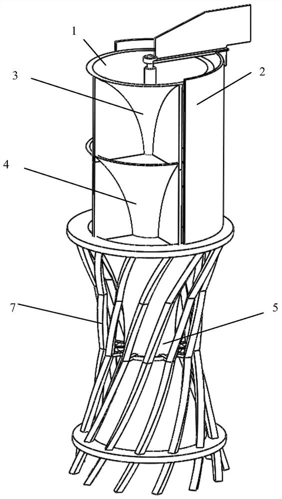
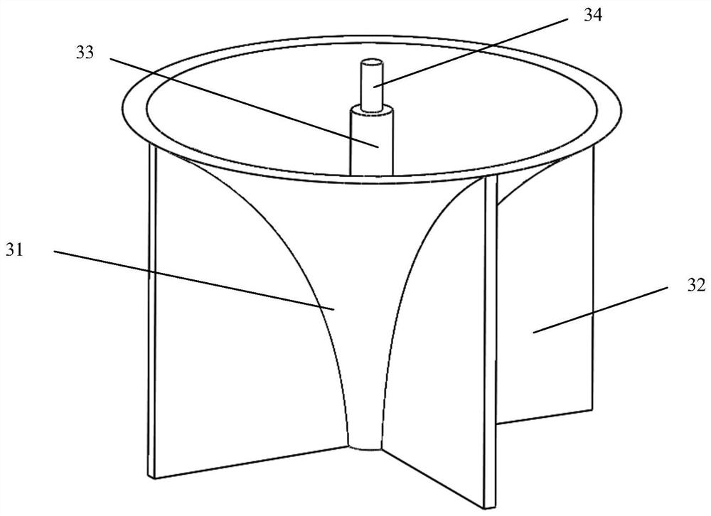
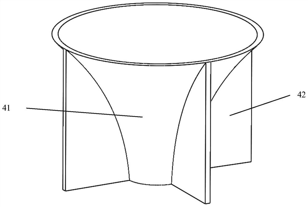
[0022] see Figure 1 to Figure 6 , an energy collection device utilizing wind energy and light energy to generate electricity, an energy collection device using wind energy and light energy to generate electricity, comprising a rotating wind blocking device 2, an upper wind guiding device 3, a lower wind guiding device 4 and a wind energy accelerating device 5; The upper wind guiding device 3, the lower wind guiding device 4 and the wind energy accelerating device 5 are stacked from top to bottom.

[0023] Both the upper air guide device 3 and the lower air guide device 4 include a main body and several air guide plates, the main body is in the shape of a trumpet, and the bell mouth is located on the top of the main body; on the outside of the main body, there are several Wind deflectors, one side of each wind deflector is connected to the outer surface of the main body, so that the...


PUM


Abstract

The invention discloses an energy collecting device utilizing wind energy and light energy to generate power. The energy collecting device comprises a rotary air blocking device, an upper air guide device, a lower air guide device and a wind energy accelerating device. The energy collecting device is characterized in that the upper air guide device, the lower air guide device and the wind energy accelerating device are superposed from top to bottom; each of the upper air guide device and the lower air guide device comprises a main body and a plurality of air guide plates, wherein the main bodyis in the form of a horn which is positioned on the top of the main body, the air guide plates are uniformly distributed in the peripheral direction outside the main body, one end of each air guide plate is connected to the outer surface of the main body, so that an area between adjacent two air guide plates becomes a wind energy collecting region; a connecting rod is axially arranged inside themain body of the upper air guide device, and the connecting rod upwards extends to form a bearing base; and a vent hole is axially formed inside the main body of the lower air guide device. The energycollecting device can be widely applied to the fields of energy and power.

Description

technical field [0001] The invention relates to an energy collection device, in particular to an energy collection device that utilizes wind energy and light energy to generate electricity. Background technique [0002] Energy is an important material basis for the survival and development of human society. Every major progress of human civilization is accompanied by important changes in energy. With the development of science and technology, human beings are paying more and more attention to the huge utilization value of renewable energy such as wind energy and solar energy. China is rich in wind energy and solar energy resources. It is reported that the total reserves of wind energy resources at 10m altitude in my country is 32.26×10 9 kw, of which the actual wind energy resource reserve that can be developed and utilized is 2.53×10 9 kw, which is especially abundant in coastal areas; in addition, the annual solar radiation received by the land surface of our country is ...

Claims


Application Information

Patent Timeline
Patent Type & Authority Applications(China)
IPC IPC(8): F03D3/04F03D3/06F03D9/00F03D80/00
CPCF03D9/007F03D3/0436F03D3/061F03D3/062F03D80/00Y02E10/74
Inventor 朱恂苏勇剑韩煜熊丁林张瑞辰谭林胡凯恒孙宇航
Owner CHONGQING UNIV
Why Eureka
Try Eureka