
Stage lighting system

A stage lighting and light source technology, which is applied in the field of stage lights, can solve problems such as overheating and damage to the light source, and achieve the effects of preventing device oxidation, prolonging life, and avoiding damage

Inactive Publication Date: 2021-01-22
GUANGZHOU GTD CULTURE & TECHNOLOGY GROUP CO LTD
View PDF7 Cites 1 Cited by
  • Summary
  • Abstract
  • Description
  • Claims
  • Application Information

AI Technical Summary

Problems solved by technology

[0004] In view of this, the embodiment of the present invention provides a stage lighting system, which solves the technical problem in the prior art that the optical axis of the optical path of the light source is on the same line as the optical axis of the light source, which easily leads to overheating and damage to the light source.

Method used


Image

  • Stage lighting system
  • Stage lighting system
  • Stage lighting system

Examples


Embodiment 1

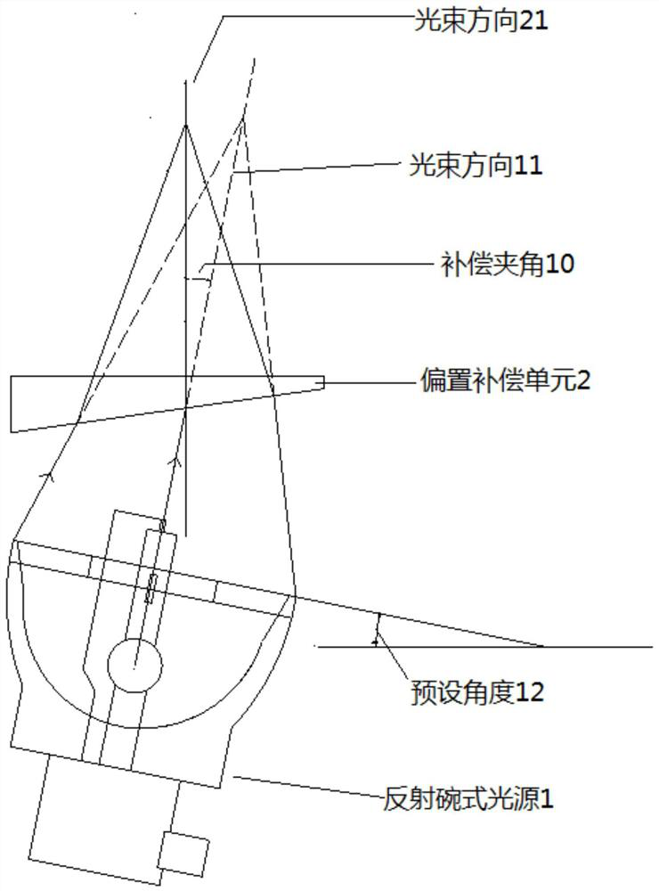
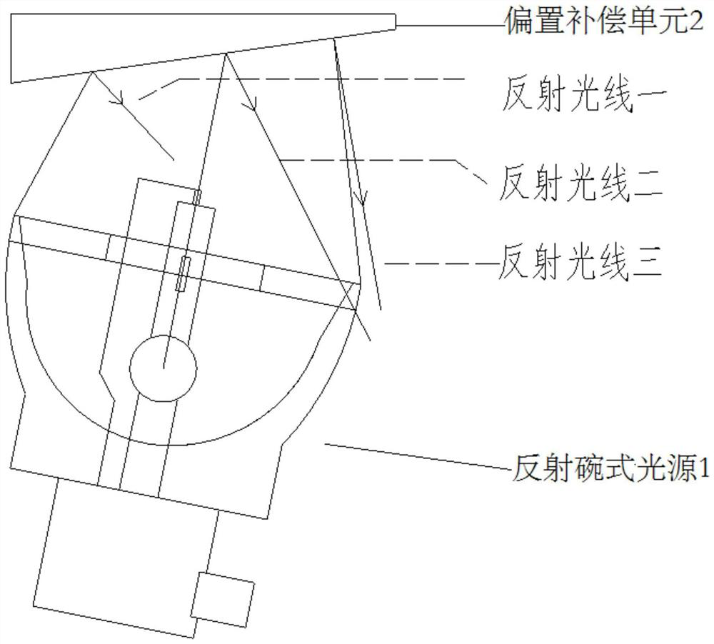
[0031] An embodiment of the present invention provides a stage lighting system, such as figure 1 As shown, the stage lighting system includes: a reflective bowl light source 1 and a bias compensation unit 2, the reflective bowl light source 1 is used to emit light beams; the bias compensation unit 2 is used to refract the light beam emitted by the reflective bowl light source 1, The compensation angle 10 between the beam direction (main optical axis direction) 21 refracted by the offset compensation unit 2 and the beam direction (original optical axis direction) 11 emitted by the reflective bowl light source 1 is greater than 0 degrees and less than 30 degrees. Among them, the reflective bowl light source 1 mainly relies on the center of the bulb to emit light and gather light through the reflective bowl at the focal point. The light output is a conical structure from the focal point to the plane of the reflective bowl lamp cup. The optical axis is perpendicular to the plane of...

Embodiment 2

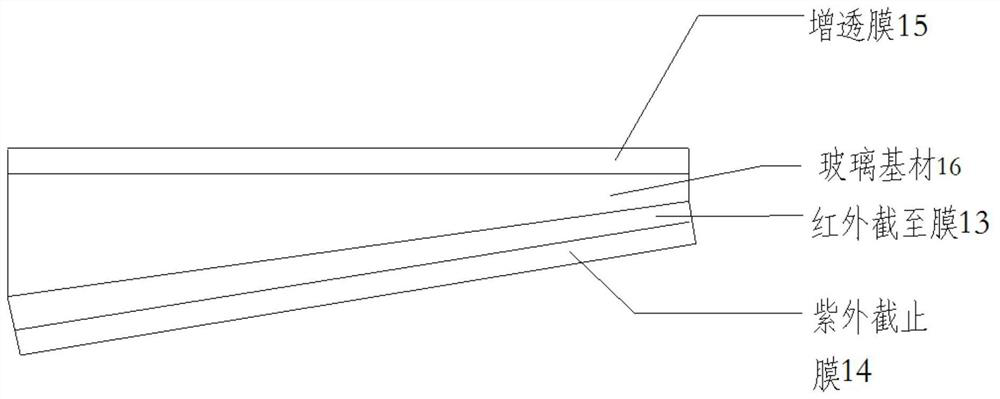
[0044] An embodiment of the present invention provides a stage lighting system, such as Figure 5 As shown, it includes: reflective bowl light source 1, offset compensation unit 2, heat dissipation unit, focusing lens 5 and fixed lens 6, reflective bowl light source 1 is placed obliquely so that the angle between the direction of the light beam emitted by the light source and the horizontal direction is 75 degrees, that is, the angle between the offset angle of the light source and the compensation angle is 15 degrees. The bias compensating unit 2 is arranged in the light source emitting direction, and is used for refracting the light beam emitted by the light source, so that the direction of the emitted light beam is perpendicular to the horizontal direction. The bias compensation unit 2 can be a trapezoidal structure or a triangular prism structure with two non-parallel surfaces in section, and is made of glass material. At the same time, one side is coated with an infrared ...

Embodiment 3

[0048] An embodiment of the present invention provides a stage lighting system, such as Figure 4 As shown, it includes: a plurality of reflective bowl light sources 1, a composite offset compensation lens, a focusing unit 3, a functional unit 4, a focusing lens 5, and a fixed lens 6. The output of multiple reflective bowl light sources 1 is placed obliquely so that the light source The angle between the direction of the outgoing light beam and the horizontal direction is 75 degrees, that is, the angle between the offset angle of the light source and the compensation angle is 15 degrees. The composite offset compensation lens is composed of a plurality of offset compensation lenses, and the plurality of offset compensation lenses are respectively arranged in multiple light source exit directions for refracting the output beam of the light source so that the beam direction of the exit lens is perpendicular to the horizontal direction. The offset compensation lens can be a trape...


PUM


Abstract

The invention discloses a stage lighting system which comprises a reflection bowl type light source and a bias compensation unit. The reflection bowl type light source is used for emitting a light beam. The bias compensation unit is used for refracting the light beam emitted by the reflection bowl type light source, and the compensation included angle between the direction of the light beam refracted by the bias compensation unit and the direction of the light beam emitted by the reflection bowl type light source is larger than 0 degree and smaller than 30 degrees. By implementing the invention, the bias compensation unit is arranged in the emitting direction of the reflection bowl type light source, and the position relationship between the bias compensation unit and the reflection bowl type light source is set, so that the direction of the light beam refracted by the bias compensation unit and the direction of the light beam emitted by the reflection bowl type light source form an included angle, therefore, most of reflected light emitted by the reflection bowl type light source and irradiated to the bias compensation unit deviates from a lamp wick of the light source, heat dissipation key parts of the light source such as a glass bulb body, a metal lead and a molybdenum sheet are avoided, the heat dissipation problem of the light source is effectively solved, damage to the light source is avoided, and the service life of the light source is prolonged.

Description

technical field [0001] The invention relates to the technical field of stage lights, in particular to a stage light system. Background technique [0002] With the improvement of people's living standards, the vigorous development of the landscape and entertainment industry has promoted the progress of stage equipment. The stage is an important stage equipment, and stage lights have always been brighter, lighter, smaller, lower power consumption, quieter, and more Economical, more intelligent and other directions of development. Brightness is an important indicator of stage lighting. In order to improve the brightness of stage lighting, light source manufacturers have been working hard to improve the luminous efficiency and power of the light source. As the power of the light source increases, a reliable heat dissipation system for the light source is a challenge. In the case of ensuring the reliability of the lamp, it is another challenge to make the size of the lamp smalle...

Claims


Application Information

Patent Timeline
Patent Type & Authority Applications(China)
IPC IPC(8): F21S8/00F21V5/00F21V5/02F21V9/40F21W131/105F21W131/406
CPCF21S8/00F21V5/00F21V5/02F21V9/40F21W2131/105F21W2131/406
Inventor 陈浩朱杰辉沈庆云
Owner GUANGZHOU GTD CULTURE & TECHNOLOGY GROUP CO LTD
Learn More