
Power distribution room with dehumidification and ventilation system

A technology for ventilation system and power distribution room, which is applied in the direction of waterway system, substation/distribution device shell, substation/switchgear cooling/ventilation, etc., can solve the problem of resource waste, ensure safe and reliable operation, avoid resource Waste, avoid direct sunlight effect

Active Publication Date: 2021-01-22
SUZHOU SAIRONG CONSTITUTION&DECORATION ENG CO LTD
View PDF5 Cites 4 Cited by
  • Summary
  • Abstract
  • Description
  • Claims
  • Application Information

AI Technical Summary

Problems solved by technology

In addition, in order to reduce direct sunlight, most power distribution rooms do not have windows, which adds a lot of difficulty to the work of maintenance personnel even in the daytime, such as self-distribution lights or flashlights, which will cause waste of resources

Method used


Image

  • Power distribution room with dehumidification and ventilation system
  • Power distribution room with dehumidification and ventilation system
  • Power distribution room with dehumidification and ventilation system

Examples


Embodiment Construction

[0032] The following will clearly and completely describe the technical solutions in the embodiments of the present invention with reference to the accompanying drawings in the embodiments of the present invention. Obviously, the described embodiments are only some, not all, embodiments of the present invention. Based on the embodiments of the present invention, all other embodiments obtained by persons of ordinary skill in the art without making creative efforts belong to the protection scope of the present invention.

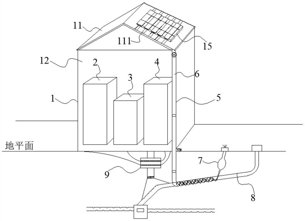
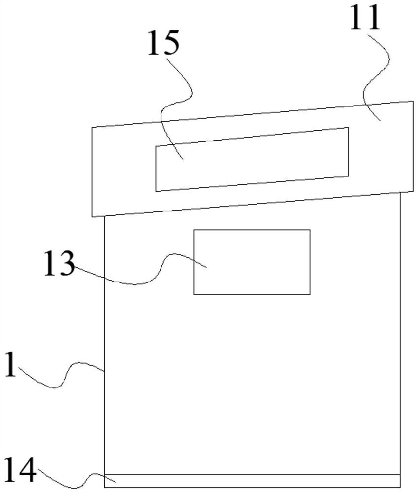
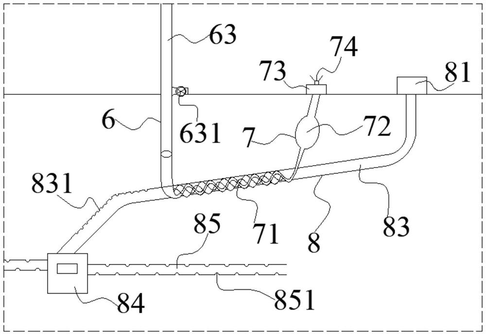
[0033] see Figure 1-7 , the present invention provides a technical solution: a power distribution room with a dehumidification and ventilation system, including a power distribution room main body 1, a high-voltage cabinet 2, a transformer 3, a low-voltage cabinet 4 and a dehumidification and ventilation system 5, the bottom of the power distribution room main body 1 and the ground In direct contact, the top of the main body 1 of the power distribution room i...


PUM


Abstract

The invention discloses a power distribution room with a dehumidification and ventilation system. The power distribution room comprises a power distribution room main body, a high-voltage cabinet, a transformer, a low-voltage cabinet and the dehumidification and ventilation system. The bottom end of the power distribution room main body is in direct contact with the ground, a slope roof is arranged at the top end of the power distribution room main body, and the side wall of the power distribution room main body, the slope roof and the ground jointly define a power distribution room inner cavity; the high-voltage cabinet, the transformer and the low-voltage cabinet are arranged in the power distribution room inner cavity, and the dehumidification and ventilation system is arranged outsidethe power distribution room main body; ventilation openings are formed in the upper ends of the side walls of the power distribution room main body and provided with fine grids, and an anti-static floor is laid at the bottom end of the power distribution room inner cavity. According to the invention, natural resources are fully combined and utilized to form a complete set of ventilation and dehumidification system, safe and reliable operation of the power distribution room can be ensured, and the power utilization safety of users is improved; besides, convenience is provided for maintenance work, unnecessary resource waste is avoided, a lighting window is formed in the roof of the power distribution room, and a special sunshade blade curtain is arranged, so that lighting can be guaranteed,and direct sunlight irradiation can also be avoided.

Description

technical field [0001] The invention relates to the technical field of power equipment, in particular to a power distribution room with a dehumidification and ventilation system. Background technique [0002] At present, electricity is already an indispensable part of people's daily life. Countless household appliances cannot operate without electricity, and the power distribution room is one of the core equipment for power system control, covering every corner of every city. However, the structure of the traditional power distribution room is not reasonable enough, and the ventilation system is not perfect, which leads to the temperature in the power distribution room being too high, resulting in potential safety hazards, and is easily affected by the surrounding environment, especially in the rainy season. The power distribution room should adopt natural ventilation, and the temperature difference between the inlet air and the exhaust air should not be greater than 15°C. ...

Claims


Application Information

Patent Timeline
Patent Type & Authority Applications(China)
IPC IPC(8): H02B1/28H02B1/56E04H1/12E04B7/02E04D13/03E04D13/04E03B3/02E03F5/10
CPCH02B1/28H02B1/565B01D49/00B01D53/002B01D53/265B03C3/04B03C3/34B01D2258/06Y02A20/108E04H5/04
Inventor 韩迎迎
Owner SUZHOU SAIRONG CONSTITUTION&DECORATION ENG CO LTD
Learn More