A push-pull DC autotransformer

An autotransformer and push-pull technology, applied in transformers, fixed transformers, transformers/inductor coils/windings/connections, etc., can solve the problems of high total cost, complex control strategy, and high cost of converters, and achieve The effect of simplifying the analysis of power transmission characteristics, reducing the required number of DC voltage components and sub-modules, and reducing the cost

Active Publication Date: 2022-05-31
HUAZHONG UNIV OF SCI & TECH
View PDF0 Cites 0 Cited by
  • Summary
  • Abstract
  • Description
  • Claims
  • Application Information

AI Technical Summary

Problems solved by technology

First, the rated capacity of the two converters must be equal to the rated DC power of the interconnection between the first DC system and the second DC system, and the rated DC voltage of the converters must be equal to the rated voltage of the connected DC system. higher overall cost
Secondly, all the transmitted DC power needs to go through DC / AC / DC two-stage power conversion, which results in large operating loss and low transmission efficiency.
[0006] To sum up, the existing mainstream high-voltage high-power DC transformers have at least one of the following defects, such as complex control strategies, high cost, high operating loss, and low transmission efficiency.

Method used


Image

  • A push-pull DC autotransformer
  • A push-pull DC autotransformer
  • A push-pull DC autotransformer

Examples


Embodiment Construction

[0052] In order to make the objectives, technical solutions and advantages of the present invention clearer, the present invention will be further described in detail below with reference to the accompanying drawings and embodiments. It should be understood that the specific embodiments described herein are only used to explain the present invention, but not to limit the present invention. In addition, the technical features involved in the various embodiments of the present invention described below can be combined with each other as long as they do not conflict with each other.

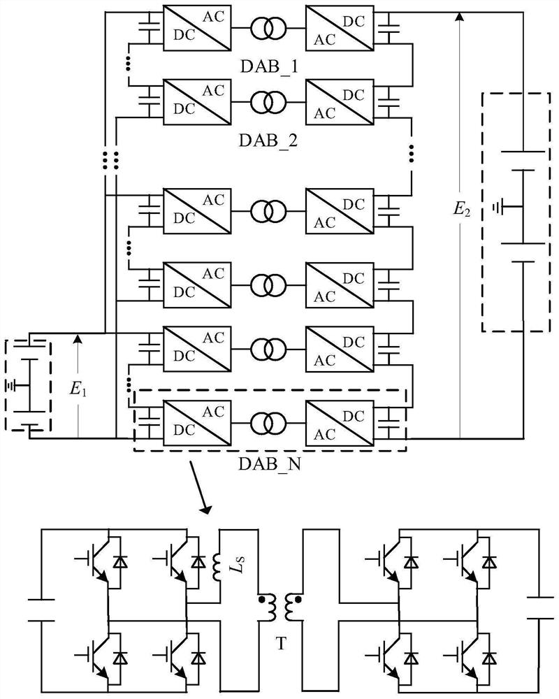
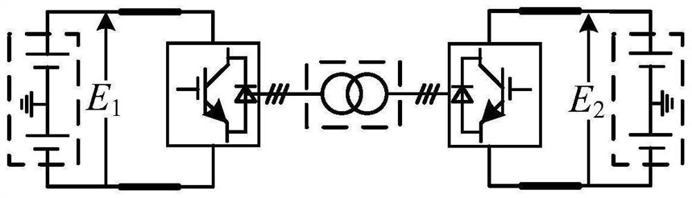
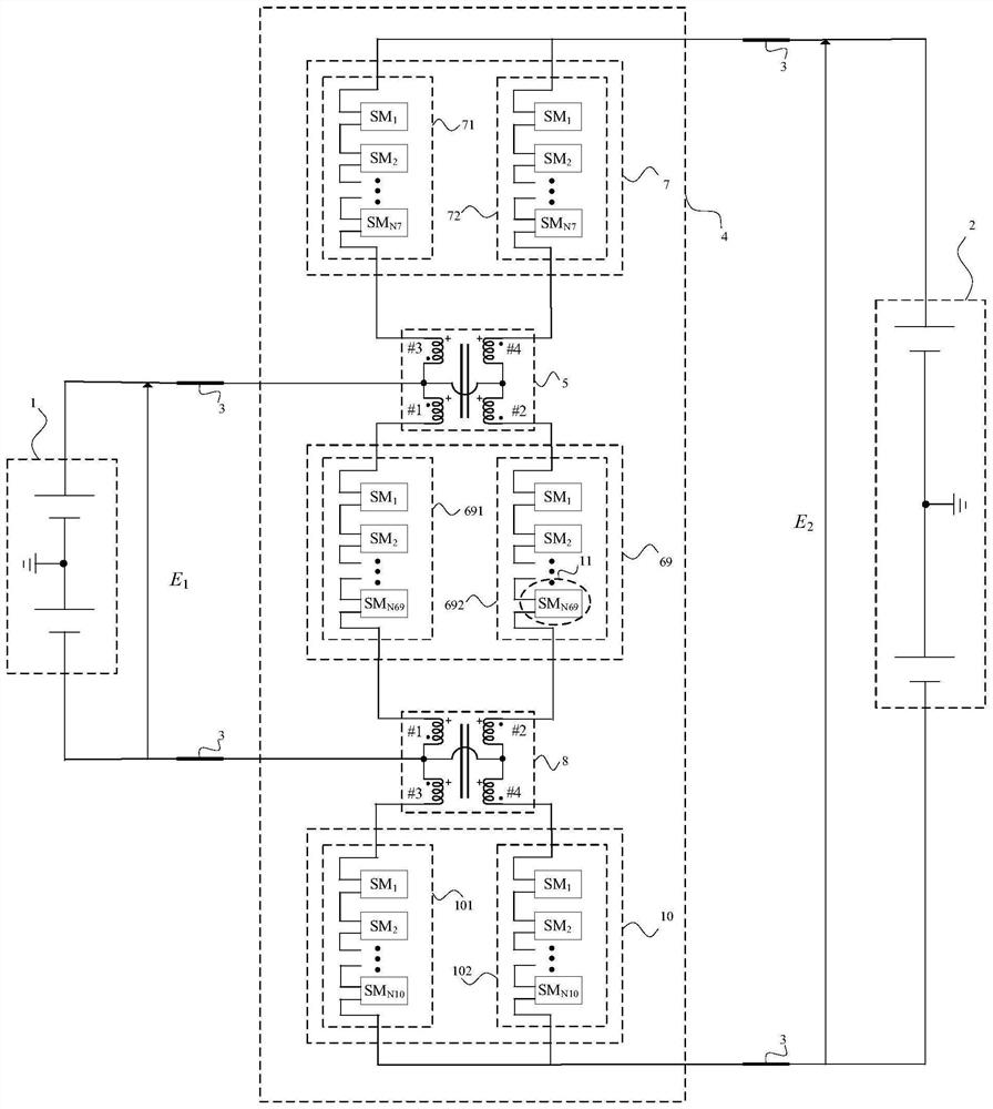
[0053] The push-pull DC autotransformer provided by the example of the present invention is mainly used for the interconnection of DC systems with different rated DC voltage levels and the control of power transmission, which can effectively solve the complex control strategies, complex control strategies, and problems of the existing DC-DC converter technology. It has the disadvantages of high cost...


PUM


Abstract

The invention discloses a push-pull DC autotransformer, which includes first, second and third power exchange units and positive and negative four-winding transformers, wherein the positive two ports of the first power exchange unit are connected to the positive pole of the second DC system The two negative ports of the first power exchange unit are connected to the two positive ports of the second power exchange unit through the positive four-winding transformer, and the two positive ports of the third power exchange unit are connected to the second power exchange unit through the negative four-winding transformer. The two ports of the negative pole of the exchange unit are connected, the positive poles of the four-winding transformer windings 1 and 2, the negative poles of the windings 3 and 4, and the positive pole of the first DC system are interconnected together, and the negative poles of the four-winding transformer windings 1 and 2 are interconnected. , the positive poles of the third and fourth windings, and the negative pole of the first DC system are interconnected together. The converter of the invention adopts the DC auto-coupling technology, which significantly reduces the commutation capacity, operation loss and total cost of the system.

Description

technical field [0001] The invention belongs to the technical field of power system power transmission and distribution, and more particularly, relates to a push-pull DC autotransformer. Background technique [0002] With the rapid development of new energy power generation, High Voltage Direct Current Transmission (HVDC) technology has received extensive attention and research from the society, and many HVDC transmission lines have been constructed and operated around the world. At the same time, with the maturity of flexible DC transmission technology and the successful trial operation of multi-terminal DC transmission systems, the technical feasibility and advantages of building a DC power grid by interconnecting different DC transmission systems are becoming more and more obvious. Large-capacity and multi-voltage levels are one of the future development trends of DC power grids, and DC transformers (or DC-DC converters), as an indispensable key technical equipment for in...

Claims


Application Information

Patent Timeline
Patent Type & Authority Patents(China)
IPC IPC(8): H02J1/00H02M3/24H01F30/02H01F27/28
CPCH02J1/00H02M3/24H01F30/02H01F27/28H02M1/0074Y02E60/60
Inventor 文劲宇韩鸣宇左文平周猛肖遥遥
Owner HUAZHONG UNIV OF SCI & TECH
Why Eureka
Try Eureka