Motor drive control circuit and system

A technology of motor drive control and main control circuit, applied in control system, vector control system, motor generator control, etc., can solve problems such as poor drive reliability, achieve strong drive reliability and avoid harmonic interference

Inactive Publication Date: 2021-01-22
GREE ELECTRIC APPLIANCES INC
View PDF4 Cites 1 Cited by
  • Summary
  • Abstract
  • Description
  • Claims
  • Application Information

AI Technical Summary

Problems solved by technology

[0005] Based on this, it is necessary to provide a motor drive control circuit and system for the problem of poor driving reliability of the traditional motor drive method

Method used


Image

  • Motor drive control circuit and system
  • Motor drive control circuit and system
  • Motor drive control circuit and system

Examples


Embodiment Construction

[0029] In order to facilitate the understanding of the present application, the present application will be described more fully below with reference to the relevant drawings. Preferred embodiments of the application are shown in the accompanying drawings. However, the present application can be embodied in many different forms and is not limited to the embodiments described herein. On the contrary, the purpose of providing these embodiments is to make the understanding of the disclosure of the application more thorough and comprehensive.

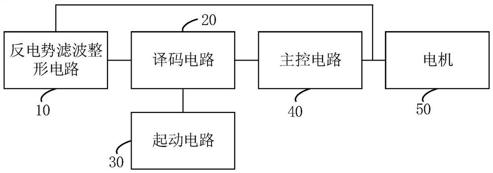
[0030] see figure 1 , a motor drive control circuit, comprising: a back EMF filter shaping circuit 10, a decoding circuit 20, a starting circuit 30 and a main control circuit 40, the output end of the back EMF filter shaping circuit 10 is connected to the first input end of the decoding circuit 20 , the second input end of the decoding circuit 20 is connected to the starting circuit 30, the output end of the decoding circuit 20 is connect...


PUM


Abstract

The invention relates to a motor drive control circuit and system. According to the invention, a starting circuit is arranged at the front end of a motor; the starting circuit can control the motor tobe started to generate induced electromotive force when the motor working in a counter electromotive force commutation mode is static, a corresponding observation waveform is obtained, and therefore,rotor position information of the motor is obtained; and meanwhile, a back electromotive force filtering and shaping circuit is arranged in front of a decoding circuit, and the input end of the backelectromotive force filtering and shaping circuit is connected between a main control circuit and the motor, so processing can be carried out according to a sampling signal and a back electromotive force signal of the motor, and filtering of the sampling signal and elimination of back electromotive force pulse sharp waves are realized, and therefore, the problem of interference in the low-speed operation process of the motor is avoided. Through a technical scheme of an embodiment in the invention, the motor can be controlled to be started at a low speed to obtain the position information of the motor rotor when the motor is in a static state, filtering optimization can be carried out on signals in the operation process of the motor, harmonic interference is avoided, and high driving reliability is achieved.

Description

technical field [0001] The present application relates to the technical field of motors, in particular to a motor drive control circuit and system. Background technique [0002] With the development of power electronics technology, especially the emergence of new permanent magnet materials, the development process of permanent magnet synchronous motors has been greatly promoted. The stable operation of the permanent magnet synchronous motor control system is based on the closed-loop control system, and the most important thing in the control system is to accurately obtain the rotor position and speed signals in order to accurately identify the motor running state, so as to control the normal start of the motor and run. The position sensorless control technology has the advantage of simple structure, and it is currently widely used in the occasions of no-load and light-load starting of the motor. The position sensorless control technology refers to the completion of closed-...

Claims


Application Information

Patent Timeline
Patent Type & Authority Applications(China)
IPC IPC(8): H02P21/14H02P21/18H02P21/24H02P25/022H02P25/026H02P27/08
CPCH02P21/14H02P25/022H02P25/026H02P27/085H02P21/18H02P21/24
Inventor 夏俊贤王友明李艺文陆光应漆凌君
Owner GREE ELECTRIC APPLIANCES INC
Why Eureka
Try Eureka