Self-adjusting sun-shading system for intelligent security camera

An intelligent security and camera technology, which is applied in the fields of optical filters for photography, components of TV systems, image communication, etc. obvious problems, to achieve the effect of ensuring imaging clarity, good promotion prospects, and good shading

Active Publication Date: 2021-01-22
浙江翔路科技有限公司
View PDF6 Cites 1 Cited by
  • Summary
  • Abstract
  • Description
  • Claims
  • Application Information

AI Technical Summary

Problems solved by technology

[0003] At present, in order to avoid light from other directions entering the camera when the security camera is shooting, resulting in blurred images in the camera, a sun visor is installed on the security camera, but the position of the sun visor installed is fixed, but the light intensity is not. As a result, when the light is strong, the shading effect of the sun visor is not obvious, and when the light is weak, the sun visor hinders the lighting of the camera, which will affect the imaging clarity of the security camera

Method used


Image

  • Self-adjusting sun-shading system for intelligent security camera
  • Self-adjusting sun-shading system for intelligent security camera
  • Self-adjusting sun-shading system for intelligent security camera

Examples


Embodiment 1

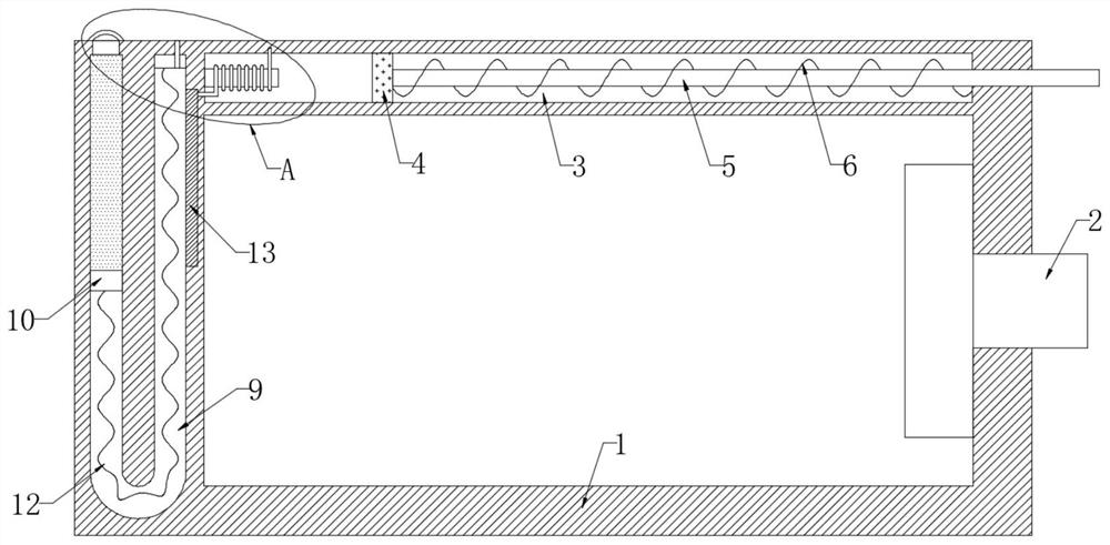
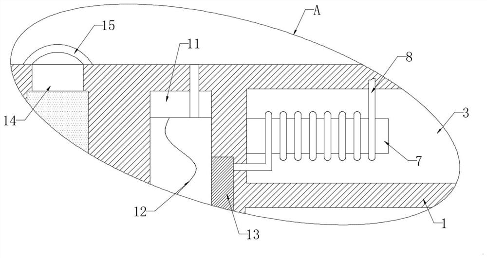
[0023] refer to Figure 1-2 , a self-adjusting sunshade system for an intelligent security camera, comprising a housing 1, the side wall of the housing 1 is fixedly connected with a camera 2, the upper end of the housing 1 is provided with a sliding plug chamber 3, and the inner wall of the sliding plug chamber 3 is slidably connected with a magnetic slider The plug 4, the side wall of the magnetic slider 4 is fixedly connected with the sun visor 5, the sun visor 5 is set through the side wall of the housing 1, the side wall of the magnetic slider 4 is elastically connected with the inner wall of the slider cavity 3 through the spring 6, and the slider cavity 3 is away from the The inner wall of the spring 6 is fixedly connected with an iron core 7, and the side wall of the iron core 7 is wound with a helical coil 8. The direction of the magnetic field of the helical coil 8 is opposite to that of the magnetic slide 4. Further, when the helical coil 8 is passed into When the cu...

Embodiment 2

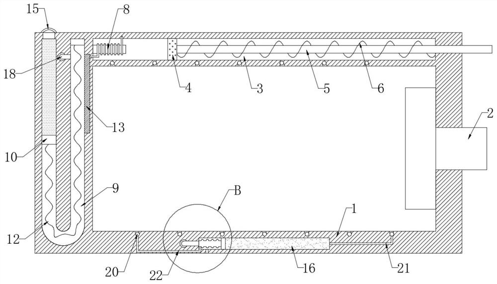
[0030] refer to Figure 3-4The difference from the first embodiment is that the lower end of the housing 1 is provided with a cooling chamber 16, the inner wall of the cooling chamber 16 is sealed and slidably connected with a slide plate 17, the side wall of the slide plate 17 is elastically connected with the inner wall of the cooling chamber 16 through a bellows 19, and the slide plate 17 is away from the corrugated Coolant is provided in the closed space formed by the side wall of the pipe 19 and the inner wall of the cooling cavity 16, the inner wall of the U-shaped cavity 9 is connected to the inner wall of the cooling cavity 16 through the intake pipe 18, and the inner wall of the housing 1 is provided with a spiral cooling cavity 20, further, The spiral setting of the spiral cooling chamber 20 increases the contact area with the inner wall of the housing 1, and at the same time prolongs the flow time of the cooling liquid in the spiral cooling chamber 20, which can bett...


PUM


Abstract

Disclosed is a self-adjusting sun-shading system for intelligent security camera. The system comprises a shell, the side wall of the shell is fixedly connected with a camera, the upper end of the shell is provided with a sliding plug cavity, the inner wall of the sliding plug cavity is slidably connected with a magnetic sliding plug, the side wall of the magnetic sliding plug is fixedly connectedwith a sun shield, and the sun shield penetrates through the side wall of the shell; the side wall of the magnetic sliding plug is elastically connected with the inner wall of the sliding plug cavitythrough a spring, an iron core is fixedly connected to the inner wall, away from the spring, of the sliding plug cavity, and a spiral coil is wound around the side wall of the iron core. The temperature of the thermal expansion liquid rises, then the thermal expansion liquid expands to push the conductive sliding block to slide on the inner wall of the U-shaped cavity, and when the conductive sliding block slides to make contact with the resistance plate, the conductive sliding block, the conductive plate and the spiral coil form a closed loop at the moment, so that current passes through thespiral coil, and a magnetic field is generated on the spiral coil; and then the magnetic sliding plug is pushed to slide, and the sun shield is pushed to slide out to carry out sun shading treatment on the camera.

Description

technical field [0001] The invention relates to the technical field of security equipment, in particular to a self-adjusting sunshade system for an intelligent security camera. Background technique [0002] The security camera is an acquisition device that converts the light image on the target surface of the image sensor from the visible light to the near-infrared spectrum range into a video image signal for the purpose of security and video surveillance. [0003] At present, in order to avoid light from other directions entering the camera when the security camera is shooting, resulting in blurred images in the camera, a sun visor is installed on the security camera, but the position of the sun visor installed is fixed, but the light intensity is not. As a result, when the light is strong, the shading effect of the sun visor is not obvious, and when the light is weak, the sun visor hinders the lighting of the camera, which will affect the imaging clarity of the security ca...

Claims


Application Information

Patent Timeline
Patent Type & Authority Applications(China)
IPC IPC(8): H04N5/225G03B11/04G03B11/02G03B17/55
CPCG03B11/04G03B11/02G03B17/55H04N23/52H04N23/50
Inventor 洪陈奇
Owner 浙江翔路科技有限公司
Why Eureka
Try Eureka