
Wearable physiological signal monitoring fingerstall

A physiological signal and wearable technology, which is applied in diagnostic recording/measurement, medical science, sensors, etc., can solve the problems of inconvenient real-time monitoring of physiological signals, error of measurement results, loose contact between light source and skin, etc., and achieve changes in mobile phone display and Bluetooth data sending and receiving methods, ensuring accuracy, and improving the effect of data sending and receiving methods

Pending Publication Date: 2021-01-26
成都子源电子科技有限公司
View PDF0 Cites 1 Cited by
  • Summary
  • Abstract
  • Description
  • Claims
  • Application Information

AI Technical Summary

Problems solved by technology

The smart bracelet collects physiological signals at the wrist, which is easy to carry, but the light source is not in firm contact with the skin, and the blood vessels in the human wrist are relatively small and deep, so the measurement results will be affected by various external factors. When it is deep or the arm shakes, it will cause errors in the measurement results.
Physiological signal acquisition The finger clip collects physiological signals at the finger. There are many shallow blood vessels in the human finger, and the measurement result is more accurate. However, due to the excessive size of the finger clip, when using the finger clip to measure physiological parameters, it will affect normal life and work. , it is inconvenient to realize real-time monitoring of physiological signals

Method used


Image

  • Wearable physiological signal monitoring fingerstall
  • Wearable physiological signal monitoring fingerstall
  • Wearable physiological signal monitoring fingerstall

Examples


Embodiment Construction

[0021] The following will clearly and completely describe the technical solutions in the embodiments of the present invention with reference to the accompanying drawings in the embodiments of the present invention. Obviously, the described embodiments are only some, not all, embodiments of the present invention. Based on the embodiments of the present invention, all other embodiments obtained by persons of ordinary skill in the art without creative efforts fall within the protection scope of the present invention.

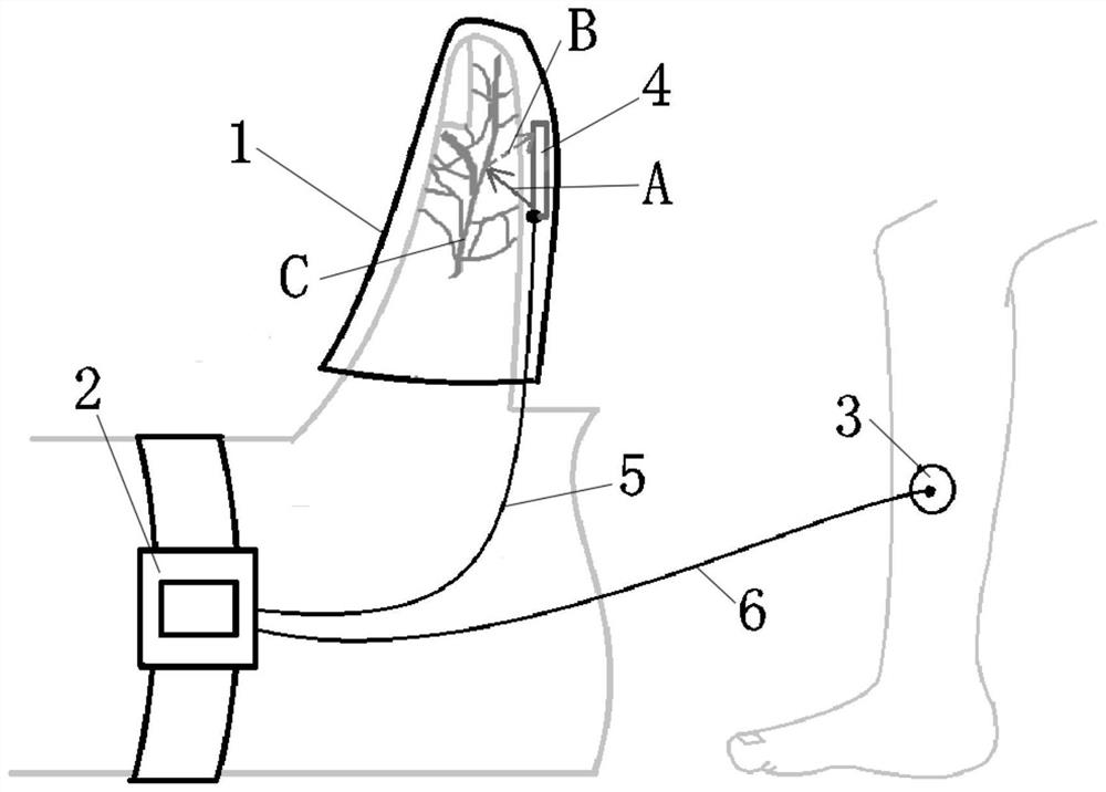
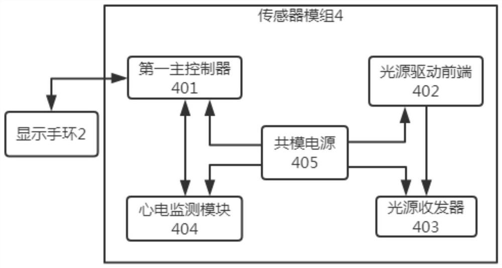
[0022] see Figure 1-3 , the present invention provides a technical solution: a wearable physiological signal monitoring finger cuff, including a monitoring finger cuff 1, a display bracelet 2, and an electrode sheet 3. A light shielding layer is provided inside the monitoring finger cuff 1 to prevent the collection of physiological signals from The light and optical path are polluted to improve the accuracy of physiological signal detection. The monitoring finger ...


PUM


Abstract

The invention relates to the technical field of dynamic monitoring equipment, in particular to a wearable physiological signal monitoring fingerstall. Thewearable physiological signal monitoring fingerstall comprises a monitoring fingerstall body, a display bracelet and an electrode slice. A light shielding layer is arranged in the monitoring fingerstall body and used for preventing light and a light path for collecting physiological signals from being polluted and improving the accuracy of physiological signal detection. A sensor module is arranged in the monitoring fingerstall body, and comprises a first main controller, a light source driving front end, a light source transceiver, an electrocardiogram monitoring module and a common-mode power supply. The display bracelet comprises a second main controller, a positioning module, a communication module, a display module and a right leg driving interface. Compared with a smart wristband, the monitoring fingerstall has the advantages that a measurement mode is improved, the sensor module is attached to a finger by means of the fingerstall, a light source makes close contact with the skin in the movement process of a person to be measured, and the stability of data in the measurement process is guaranteed; and the data receiving and sending mode is improved,a communication module and a positioning module are integrated, recordingcan be performed for a long time remotely, and real-time tracking positioning is achieved.

Description

technical field [0001] The invention relates to the technical field of dynamic monitoring equipment, in particular to a wearable physiological signal monitoring finger cuff. Background technique [0002] Physiological signal monitoring equipment is used to measure physiological parameters such as heart rate, electrocardiogram, pulse and blood oxygen saturation of the human body, and compare them with the normal fluctuation range of physiological signals. If the measured value is not within the normal range, an alarm can be issued. With the development of modern technology, physiological signal monitoring equipment tends to be simplified and portable, so that people can observe their body changes at any time. [0003] At present, most of the physiological signal detection devices on the market are divided into two types, one is a smart bracelet that collects physiological signals on the wrist, and the other is a finger clip that collects physiological signals on the fingers. ...

Claims


Application Information

Patent Timeline
Patent Type & Authority Applications(China)
IPC IPC(8): A61B5/0205A61B5/00A61B5/01A61B5/318A61B5/1455
CPCA61B5/6826A61B5/1455A61B5/02055A61B5/01
Inventor 杜亚东
Owner 成都子源电子科技有限公司
Learn More