Printing device for surfaces of lithium batteries

A printing device and lithium battery technology, applied in the field of printing devices, can solve problems such as being easily eliminated by the market, unfavorable for diversified production of enterprises, unfavorable for sustainable development of enterprises, etc., and achieve the effect of preventing deformation

Active Publication Date: 2021-01-26
东营昆宇电源科技有限公司 +1
View PDF18 Cites 4 Cited by
  • Summary
  • Abstract
  • Description
  • Claims
  • Application Information

AI Technical Summary

Problems solved by technology

[0005] In order to overcome the shortcomings that the current device can only print one type of lithium battery, which is not conducive to the diversified production of enterprises, is easy to be eliminated by the market, and is not conducive to the sustainable development of enterprises, the technical problem to be solved is: to provide an adaptable Printing device for the surface of various types of lithium batteries

Method used


Image

  • Printing device for surfaces of lithium batteries
  • Printing device for surfaces of lithium batteries
  • Printing device for surfaces of lithium batteries

Examples


Embodiment 1

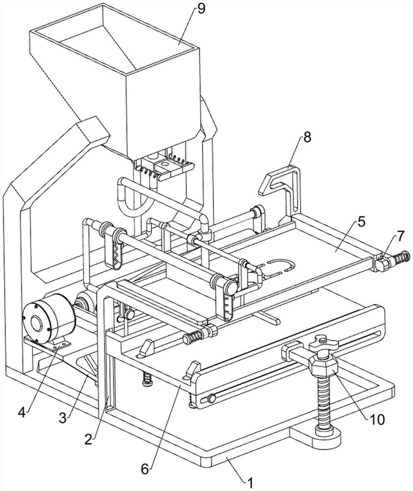
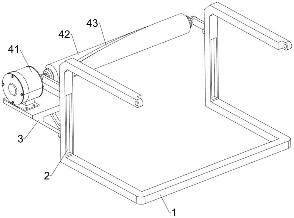
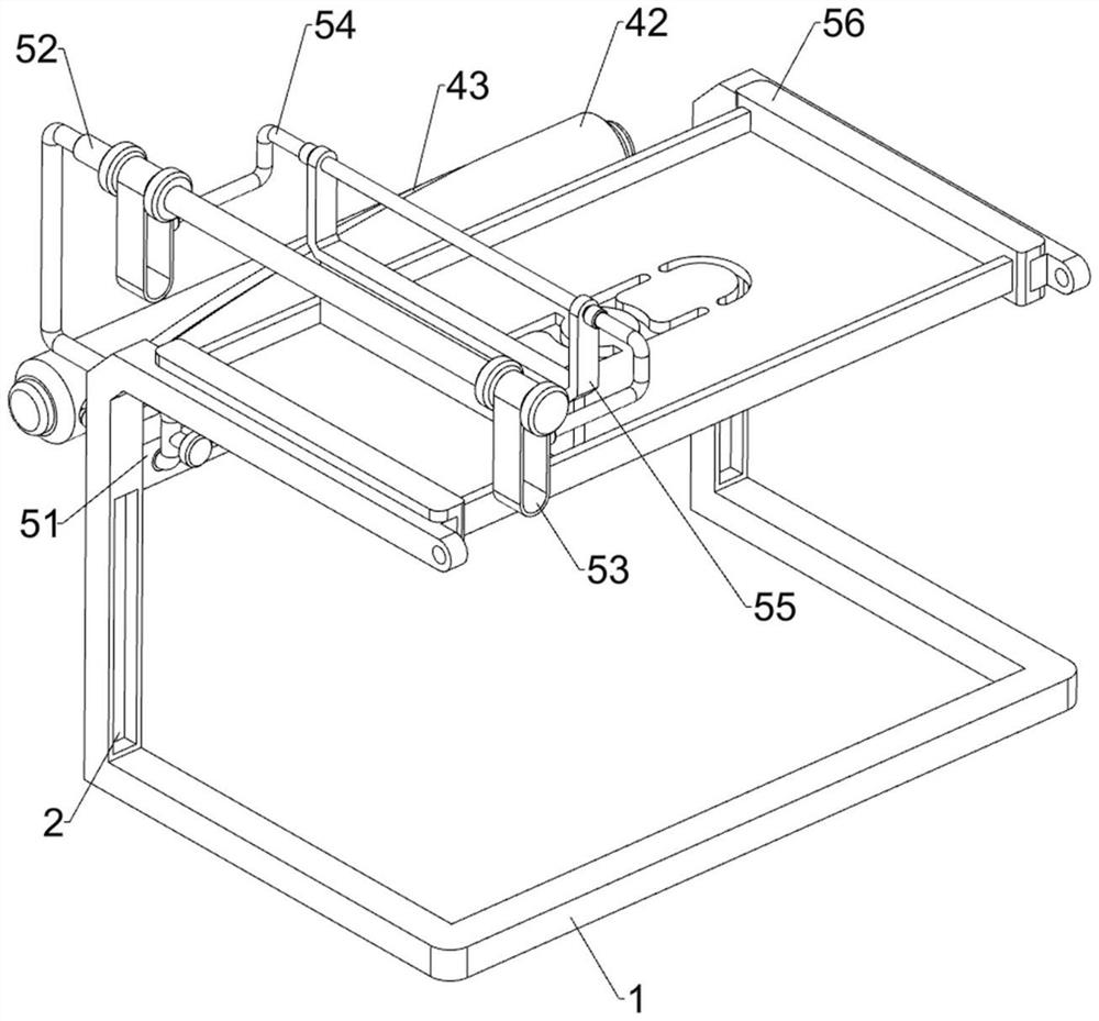
[0028] A printing device for the surface of lithium batteries, such as Figure 1-3 As shown, it includes a frame 1, a mounting plate 3, a drive assembly 4 and a printing assembly 5. The front and rear sides of the middle of the frame 1 are provided with chute 2, and the front side of the frame 1 is fixed with a mounting plate 3 by bolts. , the upper side of the mounting plate 3 is installed with a drive assembly 4, and the upper side of the right part of the frame 1 is installed with a printing assembly 5.

[0029] When printing a lithium battery, put the lithium battery under the printing assembly 5, then apply the paint on the printing assembly 5, start the driving assembly 4, and the driving assembly 4 will drive the printing assembly 5 to operate, and at the same time control the printing of the lithium battery. As the component 5 rotates, the printing component 5 will print the lithium battery, and then repeat the above operation to print another lithium battery. When all...

Embodiment 2

[0035] On the basis of Example 1, such as figure 1 , Figure 4 , Figure 5 , Figure 6 , Figure 7 and Figure 8 As shown, a placement assembly 6 is also included, and the placement assembly 6 includes a placement plate 61, a second guide rail 62, a blocking plate 63, a right-angle rod 64, a slide bar 65, a wedge block 66 and a first spring 67, between the chute 2 The sliding type is provided with a placement plate 61, the first special-shaped rod 52 is slidingly connected with a second guide rail 62, the rear side of the second guide rail 62 is connected with a blocking plate 63, and the lower side of the second guide rail 62 is connected with a right-angle rod 64, the right-angle The left and right sides of bar 64 are all slidably installed with slide bar 65, and the upper side of slide bar 65 is welded with wedge block 66, and wedge block 66 cooperates with placement plate 61, is connected with first spring between slide bar 65 and right-angle bar 64 67.

[0036] Cont...


PUM


Abstract

The invention relates to a printing device, in particular to a printing device for the surfaces of lithium batteries, and aims to solve the technical problem of how to provide a printing device capable of adapting to the surfaces of various types of lithium batteries. The printing device for the surfaces of the lithium batteries comprises a rack, a mounting plate, a driving assembly and a printingassembly, wherein sliding grooves are formed in the two sides of the rack; the mounting plate is mounted on the rack; the driving assembly is mounted on the mounting plate; and the printing assemblyis mounted on the rack. The printing device is provided with a clamping assembly, a new template can be replaced and clamped, so that the template cannot loose, and deformation caused by printing is prevented; the printing device is provided with a pushing assembly, and damage to a printing plate due to the fact that the printing plate makes contact with the rack when moving to the edge can be prevented; and the printing device is provided with an adjusting assembly, so that the device can adapt to different types of batteries, and enterprises can carry out diversified production.

Description

technical field [0001] The invention relates to a printing device, in particular to a printing device for the surface of a lithium battery. Background technique [0002] A lithium battery is a battery that uses lithium metal or lithium alloy as the anode material and uses a non-aqueous electrolyte solution. The difference between lithium battery and lithium ion battery is that the former is a primary battery and the latter is a rechargeable battery. When producing lithium batteries, it is necessary to print the produced lithium batteries so that buyers can know the model and other information of the lithium batteries. [0003] The current printing device used on the surface of lithium batteries can only print one type of lithium battery. When the model needs to be changed, the equipment needs to be replaced, which is not conducive to the diversified production of the enterprise, resulting in a single product of the enterprise, which is easy to be eliminated by the market. ...

Claims


Application Information

Patent Timeline
Patent Type & Authority Applications(China)
IPC IPC(8): B41F17/00H01M6/00H01M6/14H01M10/54B67D3/00
CPCB41F17/00H01M10/54H01M6/14H01M6/005B67D3/00Y02W30/84
Inventor 彭荣辉
Owner 东营昆宇电源科技有限公司
Why Eureka
Try Eureka