
Portal frame device for mechanical automatic machining

A gantry and mechanical technology, applied in the direction of lifting equipment braking device, hoisting device, transportation and packaging, etc., can solve the problems of no shock absorption device, unbalanced force on the top beam of the gantry, rolling staff, etc., to avoid Deformation or even breakage, easy and stable winding operation, and increased safety in use

Pending Publication Date: 2021-01-26
李闯
View PDF0 Cites 4 Cited by
  • Summary
  • Abstract
  • Description
  • Claims
  • Application Information

AI Technical Summary

Problems solved by technology

[0003] When the existing gantry device for mechanical automatic processing is used to suspend parts, in order to balance the force on the top beam of the gantry, the electric hoist is usually moved to the middle position to balance the force. Under the gravity of the components, the top beam of the gantry will be deformed or even broken due to the unbalanced force, which may crush the staff and cause major production safety accidents
[0004] The existing gantry device for mechanical automatic processing usually uses an electric hoist to lift and lower the fixed parts in the process of moving the parts, and then moves the whole gantry to move the position of the parts. The movement of the gantry is completely It is realized by the wheels fixed on the base. During the movement, the wheels have no shock absorbing device, which causes the whole gantry to sway. Since the parts and the gantry are only connected by the wire rope of the electric hoist, the parts are also easy to shake, but The parts are heavy and have high inertia, and the gantry is likely to be shaken down and injure the staff

Method used


Image

  • Portal frame device for mechanical automatic machining
  • Portal frame device for mechanical automatic machining
  • Portal frame device for mechanical automatic machining

Examples


Embodiment Construction

[0026] The following will clearly and completely describe the technical solutions in the embodiments of the present invention with reference to the accompanying drawings in the embodiments of the present invention. Obviously, the described embodiments are only some, not all, embodiments of the present invention. Based on the embodiments of the present invention, all other embodiments obtained by persons of ordinary skill in the art without making creative efforts belong to the protection scope of the present invention.

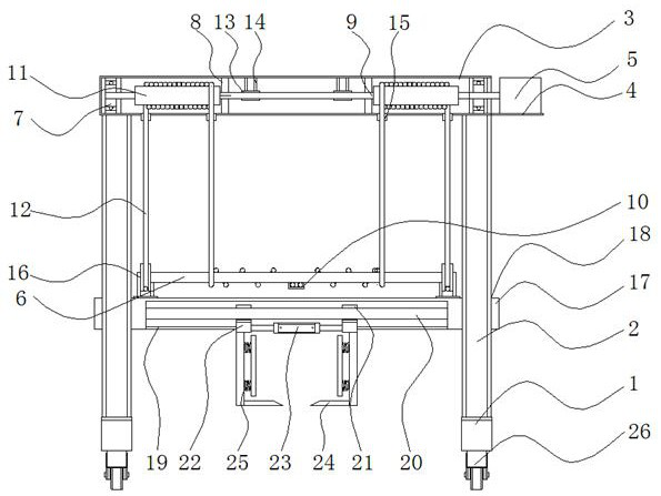
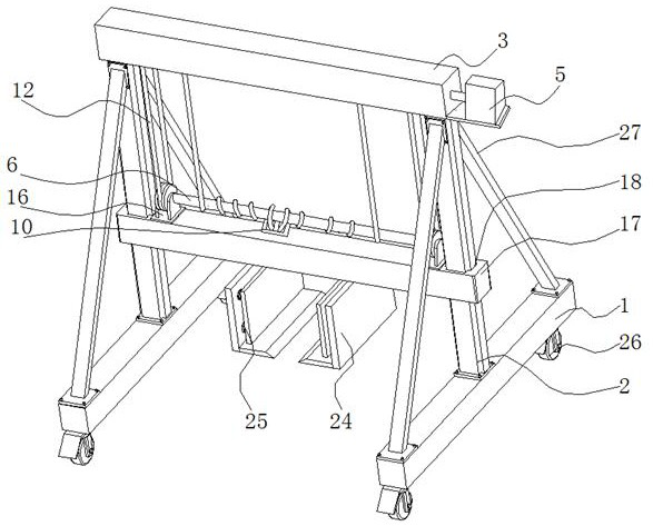
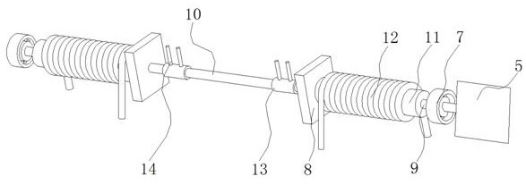
[0027] Such as Figure 1 to Figure 6As shown, the present invention provides a gantry device for mechanical automatic processing, including two bases 1, and the middle parts of the top surfaces of the two bases 1 are fixedly equipped with pillars 2, and the pillars 2 mainly serve as supporting functions. Universal wheels 26 are fixedly installed on the front and rear sides, wherein the universal wheels 26 can rotate freely and have their own brake assembly. Wh...


PUM


Abstract

The invention belongs to the technical field of mechanical automatic machining, and discloses a portal frame device for mechanical automatic machining. The portal frame device comprises two bases, wherein supporting columns are fixedly mounted in the middles of the top surfaces of the two bases, universal wheels are fixedly mounted on the front and rear sides of the bottoms of the two bases, a topbeam is fixedly mounted at the tops of the two supporting columns, and reinforcing steel pipes are fixedly connected to the front and rear sides of the tops of the bases and fixedly connected with the supporting columns. According to the portal frame device, an output shaft of a servo motor drives a rotating shaft to rotate, free winding and unwinding of steel wire ropes are achieved through rotation of wire winding devices and a connecting shaft, and then the gravity of a movable cross beam acts on the wire winding devices and the connecting shaft; compared with the prior art, acting force acting on the middle of the top beam is dispersed, and it is avoided that the middle of the top beam of the portal frame device deforms and even breaks due to long-term stress; and meanwhile, the steelwire ropes are always in a tensioned state, so that the use safety of the portal frame device is improved.

Description

technical field [0001] The invention belongs to the technical field of mechanical automatic processing, in particular to a gantry device for mechanical automatic processing. Background technique [0002] The gantry is a new type of small lifting gantry developed according to the daily production needs of small and medium-sized factories for handling equipment, warehouse import and export, lifting and maintenance of heavy equipment and material transportation. It is suitable for manufacturing parts, auto repair factories, mines, civil construction sites and occasions where lifting is required. It is commonly used in building construction as material transportation and construction personnel's up and down use to realize lifting mechanization, which can reduce manpower, reduce production and operation costs, and improve work efficiency. The process of making a change. According to the differences in processing methods, it can be divided into cutting processing and pressure pr...

Claims


Application Information

Patent Timeline
IPC IPC(8): B66C5/02B66C13/06B66C1/42B66D1/26B66D1/12
CPCB66C5/02B66C13/06B66C1/427B66D1/26B66D1/12
Inventor 李闯孙荣
Owner 李闯
Learn More