A blade tip cutting coating preparation system and application method capable of alleviating residual stress
A technology of residual stress and preparation system, applied in the direction of coating, metal material coating process, etc., can solve the problem of cracks on the tip surface of the blade, and achieve the effect of reducing residual stress and reducing heat loss.
- Summary
- Abstract
- Description
- Claims
- Application Information
AI Technical Summary
Problems solved by technology
Method used
Image
Examples
Embodiment 1
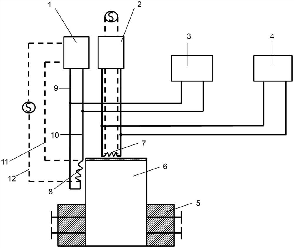
[0035] see figure 1 , a blade tip cutting coating preparation system with the effect of relieving residual stress, including a blade fixing module 5, a first induction heating head 7 and a second induction heating head 8, a refrigeration module, and a circuit control module.
[0036] The blade fixing module 5 includes a fixing block and a pin, and the fixing block is an electrically insulating bakelite board, and the fixing of the blade base 6 is realized by the pin and the fixing block; the first induction heating head 7 is located directly above the blade tip surface of the blade base 6, and the second The induction heating head 8 is located on the left side of the airfoil of the blade base 6 and is flush with the blade tip surface.
[0037]The circuit control module includes a first circuit control module 1 and a second circuit control module 2, one end of the second induction heating head 8 is connected to the output end of the first circuit control module 1 through a firs...
Embodiment 2
[0046] On the basis of Example 1, a blade tip cutting coating preparation system with the function of relieving residual stress also includes two sets of speed regulation modules. see figure 2 , the speed module includes a slide rail base 13, a belt 14, an electric slider 15, a motor 16, a controller 17, an induction heater 18, and the first induction heating head 7 or the second induction heating head 8 is fixedly installed on the electric slider 15 , the electric slider 15 is fixedly installed on the belt 14, the belt 14 is driven and installed on the slide rail base 13, the motor 16 is fixedly installed on the slide rail base 13, and the motor 16 is connected with the controller 17 in communication; when the motor 16 drives the belt 14 to move , the belt 14 drives the first induction heating head 7 or the second induction heating head 8 to move. By adjusting the rotation speed of the motor 16 by the controller 17, the rotation speed of the electric slider 15 can be change...
Embodiment 3
[0053] On the basis of Embodiment 1, in this embodiment, the second induction heating head 8 is in the shape of a strip body, and the length of the second induction heating head 8 is equal to the height of the blade matrix, and the width is 0.3cm; 8 is obliquely placed on the left side of the blade body, and the inclination angle is 5° (the upper end of the second induction heating head 8 is close to the blade tip, and the lower end of the second induction heating head 8 is away from the root of the blade body); the first induction heating head 7 is long Strip body shape, the width of the first induction heating head 7 is equal to the width of the second induction heating head 8; the first induction heating head 7 is placed in parallel directly above the blade tip surface. The first induction heating head 7 and the second induction heating head 8 move in the same direction and at the same speed of 0.5 cm / s, and the second induction heating head 8 moves 1 second earlier than the...
PUM
 Abstract
Description
Claims
Application Information
 - R&D
- Intellectual Property
- Life Sciences
- Materials
- Tech Scout
- Unparalleled Data Quality
- Higher Quality Content
- 60% Fewer Hallucinations
Browse by: Latest US Patents, China's latest patents, Technical Efficacy Thesaurus, Application Domain, Technology Topic, Popular Technical Reports.
© 2025 PatSnap. All rights reserved.Legal|Privacy policy|Modern Slavery Act Transparency Statement|Sitemap|About US| Contact US: help@patsnap.com


