High-power brushless electronic water pump

An electronic water pump, high-power technology, applied in the direction of pumps, pump devices, pump components, etc., can solve the problems of small heat dissipation area of ​​the heat sink, difficult installation, and many types of products, and achieves high power, strong magnetism, and low manufacturing difficulty. Effect

Pending Publication Date: 2021-01-26
JIANGSU LANGXIN ELECTRIC
View PDF1 Cites 4 Cited by
  • Summary
  • Abstract
  • Description
  • Claims
  • Application Information

AI Technical Summary

Problems solved by technology

[0005] 3. 3 and 201720017208.3 brushless electronic water pump Figure 4 Among them, the upper end surface of the isolation sleeve and the lower end surface of the upper cover are respectively provided with a half spiral water flow groove, and the two spiral water flow half grooves cooperate with each other to form a spiral water flow channel so as to guide the liquid flowing in from the water inlet of the upper cover to the water outlet. When this structure is fixed, the upper cover needs to be fixed on the spacer sleeve at a specific angle and position so that the spiral water flow and half grooves can cooperate with each other, and the installation is more difficult. At the same time, once the brushless electronic water pump is designed, the water inlet, water outlet and pump The relative position of the three connectors is determined, and the relative position relationship between the water inlet, water outlet and connectors of each vehicle OEM is not necessarily the same, which will lead to different assembly requirements of different vehicle OEMs. Design a variety of brushless electronic water pumps with different relative angles, resulting in a variety of products;
[0006] 4. The brushless electronic water pump in 201720017208.3 Figure 5 As shown, the heat dissipation seat 301 includes an arc-shaped heat dissipation bottom plate 3011 and heat dissipation fins 3012 arranged at the bottom of the heat dissipation bottom plate 3011. The heat dissipation bottom plate 3011 is provided with an embedded protrusion 3013, and the sealing ring 302 is set on the embedded On the protrusion 3013, the embedding protrusion 3013 is plugged into the installation through hole and fixed with the heat-conducting pressing piece 304 with screws. The heat dissipation area of ​​the heat dissipation seat of this structure is relatively small, which can meet the requirements of the electronic water pump with less power. Heat dissipation requirements, but cannot meet the heat dissipation requirements in high-power electronic water pumps
The plug is set at the bottom and integrally formed with the shell. When the brushless electronic water pump is being maintained and repaired, especially when the PCB board is overhauled, it is necessary to disassemble the upper cover, rotor, and stator of the entire electronic water pump. Replacing the PCB board makes maintenance and repair difficult
[0007] 5. In the brushless electronic water pump of 201720017208.3, the PCB board is directly positioned with the stator core through the insertion insert 4014 and the fixed embedding hole, and then the PCB board and the stator winding and the pins of the connector are welded and fixed. In this way, when in use, due to the bumping of the vehicle, the electronic water pump will vibrate violently, and the shell directly transmits the vibration to the stator core and then directly transmits it to the PCB board, which will easily lead to loosening of the soldering position of the pins and cause failures

Method used


Image

  • High-power brushless electronic water pump
  • High-power brushless electronic water pump
  • High-power brushless electronic water pump

Examples


Embodiment Construction

[0040] The present invention will be described in further detail below through specific examples.

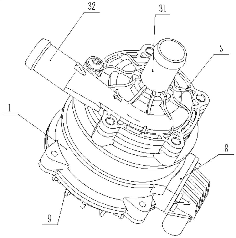
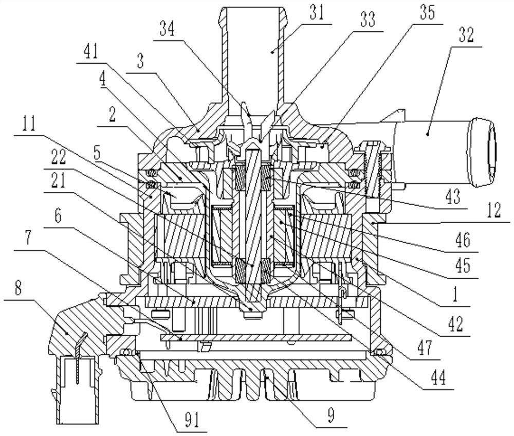
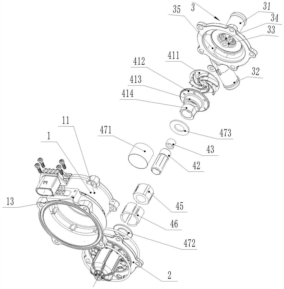
[0041] Such as Figure 1 to Figure 9 As shown, a high-power brushless electronic water pump includes a detachable and fixed shell 1, an insulating sleeve 2 and an upper cover 3, wherein the high power mentioned in the present invention is a relative concept, and is not specific to a certain power. Considering high power, the power of the brushless electronic water pump in the solution of the present invention is greater than that of the brushless electronic water pump mentioned in the background technology. The previous power was 65W, but the current brushless electronic water pump can achieve 110W.

[0042] An installation chamber is formed between the isolation sleeve 2 and the housing 1, a fluid chamber is formed between the isolation sleeve 2 and the upper cover 3, and the fluid chamber and the installation chamber are independent of each other, and the housing 1 includes ...


PUM


Abstract

The invention discloses a high-power brushless electronic water pump. The high-power brushless electronic water pump comprises a shell, an isolation sleeve and an upper cover; a mounting cavity is formed between the isolation sleeve and the shell, a fluid cavity is formed between the isolation sleeve and the upper cover, a stator assembly and a PCB are fixed in the mounting cavity, and a rotor assembly is rotationally arranged in the fluid cavity; the rotor assembly comprises an impeller and a rotor shaft sleeve, the impeller is fixed to the upper end part of the rotor shaft sleeve, and an upper wear-resisting lubricating insert and a lower wear-resisting lubricating insert are concentrically embedded into the upper end and the lower end of the rotor shaft sleeve respectively; a rotor ironcore is fixed to the periphery of the rotor shaft sleeve, sintered Ru-Fe-B magnetic steel is evenly distributed on the circumference of the circle center of the rotor iron core, and a rotor sleeve shell is fixed outside the rotor shaft sleeve; the isolation sleeve is provided with a positioning center shaft, and the positioning center shaft is inserted into a center hole; and the shell is provided with a heat dissipation device connected with the PCB in a heat conduction mode, and the shell is provided with a patch plug connected with an external wire. The brushless electronic water pump canimprove the magnetism of a rotor, and therefore the power of the brushless electronic water pump is improved.

Description

technical field [0001] The invention relates to an electronic water pump, which is used for a high-power brushless electronic water pump used in vehicles. Background technique [0002] The electronic water pump uses the magnetic interaction between the rotor and the stator to drive the impeller to rotate. The applicant applied for a brushless electronic water pump with the patent number 201720017208.3 in 2017. The rotor assembly of the brushless electronic water pump always rotates smoothly, with small rotation resistance and high water output efficiency. The electronic water pump has higher reliability and longer service life. long. However, the brushless electronic water pump still has the following disadvantages in actual use: [0003] 1. The rotor assembly includes an impeller and a connecting cylinder arranged at the bottom of the impeller. A wear-resistant lubricating insert is embedded concentrically in the inner hole of the connecting cylinder, and a wear-resistant...

Claims


Application Information

Patent Timeline
Patent Type & Authority Applications(China)
IPC IPC(8): F04D13/06F04D29/22F04D29/18F04D29/58F04D29/66F04D29/42F04D29/62F04D29/04F04D29/06H02K1/27H02K1/28
CPCF04D13/0606F04D13/0626F04D13/064F04D29/04F04D29/061F04D29/185F04D29/22F04D29/426F04D29/5813F04D29/628F04D29/669H02K1/2753H02K1/28
Inventor 丁言闯赵行行赵浩东
Owner JIANGSU LANGXIN ELECTRIC
Why Eureka
Try Eureka