Vibration sensing system with cooling shell

A vibration sensing system and vibration sensor technology, applied in cooling/ventilation/heating renovation, measuring devices, instruments, etc., can solve the problems of vibration sensor overtemperature failure, etc., to reduce thermal radiation, improve cooling effect, and reduce heat conduction. Effect

Pending Publication Date: 2021-01-26
中国船舶重工集团公司第七0三研究所
View PDF9 Cites 1 Cited by
  • Summary
  • Abstract
  • Description
  • Claims
  • Application Information

AI Technical Summary

Problems solved by technology

[0004] The purpose of the present invention is to solve the problem of over-temperature failure of the vibration sensor in the high temperature area of ​​the casing of the traditional industrial gas turbine, and to provide a vibration sensing system with a cooling shell

Method used


Image

  • Vibration sensing system with cooling shell
  • Vibration sensing system with cooling shell
  • Vibration sensing system with cooling shell

Examples


Embodiment 1

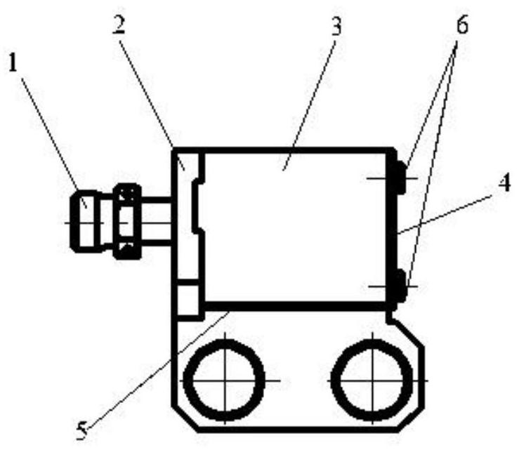
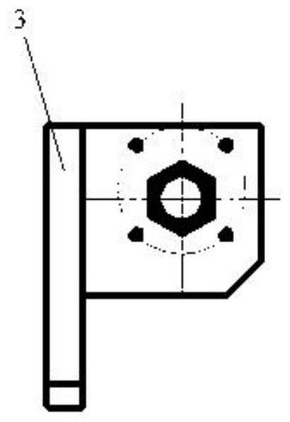
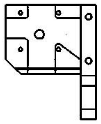
[0026] Such as Figure 1(a)-Figure 1(d) Shown is a cooling shell of a vibration sensing system with a cooling shell of the present invention, including a connecting plate 3 and an ear seat 2; the connecting plate 3 is provided with a casing mounting hole; the ear seat is installed On one side of the connection plate, a heat radiation blocking plate 5 is arranged under the ear seat, a heat radiation blocking plate 4 is arranged behind the ear seat, a pipe joint 1 is arranged outside the ear seat, and a sensor installation hole is opened in the center of the ear seat , there is a cooling airway slot around the sensor installation hole, and a process gas nozzle 8 is arranged on the side of the sensor installation hole.

[0027] The ear seat that is in direct contact with the sensor probe is specially designed, adopts a channel air-cooled structure, the ear seat is opened for ventilation and cooling, and the side that contacts the sensor is slotted to enhance the heat exchange bet...

Embodiment 2

[0029] The present invention adopts air-cooled grooved lugs and process gas nozzles for diffusing the flow field of cooling air to cool the sensor in all directions, and a thin support plate is arranged around the sensor to greatly reduce heat radiation while reducing heat conduction. Compared with the traditional sensor base, the present invention adopts multiple cooling methods in parallel to improve the cooling effect. After practical application verification, the present invention can greatly reduce the surface temperature of the sensor, effectively avoiding the problem that the measurement accuracy of the sensor is affected by excessive temperature.

[0030] The structure of the process gas nozzle arranged on the left side of the sensor and its diffusion of the convection field are shown in Fig. 4(a), Fig. 4(b) and Fig. 4(c). A total of 8 slots with a width of 1 mm are opened on the side and the side, the length of the end slot is 2 mm, and the length of the side slot is 3...

Embodiment 3

[0032] Figure 3(a), Figure 3(b) and Figure 5 Shown is a vibration sensing system with a cooling shell of the present invention, including a cooling shell and a vibration sensor 7; the cooling shell includes a connecting plate and an ear seat; the connecting plate is provided with a casing mounting hole; The ear seat is installed on one side of the connecting plate, a heat radiation blocking plate is arranged under and behind the ear seat, a sensor mounting hole is opened in the center of the ear seat, and cooling air passage slots are arranged around the sensor mounting hole. A process gas nozzle is arranged on one side of the sensor installation hole; the vibration sensor is fixed on the ear seat through the sensor installation hole, and the probe of the vibration sensor is arranged on the side of the process gas nozzle; the ear seat is provided with a pipe joint , the cooling air flow passes through the pipe joint and impacts the bottom of the vibration sensor, and then dev...


PUM


Abstract

The invention belongs to the technical field of the energy power industry, and particularly relates to a vibration sensing system with a cooling shell. According to the invention, an air-cooled slotted lug and a process gas nozzle for diffusing a flow field of cooling gas are adopted, a cooling gas channel with a special structure and a strand of cooling gas pipe are additionally arranged betweenthe sensor base and the high-temperature casing bracket, and the cooling gas pipe directly jets to the sensor base and flows out along the channel, so that convection cooling is carried out on the whole semi-open chamber; and a cooling air nozzle is arranged on the side surface of the sensor to cool the sensor again. Multiple cooling modes are adopted in parallel to improve the cooling effect, andpractical application verifies that the surface temperature of the sensor can be greatly reduced, and the problem that the measurement precision of the sensor is affected due to too high temperatureis effectively avoided.

Description

technical field [0001] The invention belongs to the technical field of energy and power industry, and in particular relates to a vibration sensing system with a cooling shell. Background technique [0002] While the industrial gas turbine rotates at high speed, it is often accompanied by vibration. In order to comprehensively monitor the operation of the unit, it is necessary to arrange vibration sensors outside the casing of the unit for measurement. The gas turbine combustor and the area of ​​the outer casing of the rear turbine belong to the high-temperature area, and the temperature on the surface of the casing reaches above 600°C. However, the cooling effect of the traditional sensor bracket is not good due to design structural defects, which often leads to vibration sensors in this area due to overheating. Warm and ineffective. [0003] In the West-to-East Gas Pipeline Project, the supercharger units using traditional vibration sensor brackets in Xinjiang Yandun Stati...

Claims


Application Information

Patent Timeline
Patent Type & Authority Applications(China)
IPC IPC(8): G01H17/00H05K7/20
CPCG01H17/00H05K7/20145H05K7/20
Inventor 汪作心吴思宇金鹏夏凯
Owner 中国船舶重工集团公司第七0三研究所
Why Eureka
Try Eureka