A method for inversion of heat source position in high temperature area of ​​goaf in underground coal mine

A technology for gobs and regions, which is applied in the field of heat source position inversion in high-temperature areas of goafs in underground coal mines. It can solve problems such as limited temperature points, immersion of optical fibers or temperature-sensing probes, and unsuitable temperature detection.

Active Publication Date: 2021-07-06
CHINA UNIV OF MINING & TECH
View PDF5 Cites 0 Cited by
  • Summary
  • Abstract
  • Description
  • Claims
  • Application Information

AI Technical Summary

Problems solved by technology

[0005] However, optical fiber temperature measurement technology is to lay optical fibers in gobs or fire-prone areas in advance, and use optical time domain reflection technology to measure the temperature of gobs in real time. Since optical fibers are generally laid on the coal seam floor, they are affected by the collapse of the coal seam roof and mine water. , this method often has problems such as the optical fiber is broken, the optical fiber or the temperature sensor is soaked, etc.
In addition, this method requires pre-embedded optical fibers, and for areas that have not been pre-embedded and have been on fire, the internal temperature cannot be measured
[0006] Infrared detection technology is only suitable for temperature measurement in areas with obvious surface temperature changes, and is not suitable for temperature detection in goafs under mines or abandoned roadways
By inserting a thermocouple into the borehole to measure the temperature, although the temperature of the fire space can sometimes be measured, the measured temperature points are limited. Due to the influence of the surrounding rock conditions of the borehole and the poor thermal conductivity of the porous medium in the goaf, this method is accurate. Poor sensitivity and sensitivity, and the measured temperature point is difficult to obtain the heat source position by ordinary numerical fitting method

Method used


Image

  • A method for inversion of heat source position in high temperature area of ​​goaf in underground coal mine
  • A method for inversion of heat source position in high temperature area of ​​goaf in underground coal mine
  • A method for inversion of heat source position in high temperature area of ​​goaf in underground coal mine

Examples


Embodiment Construction

[0027] The specific embodiments of the present invention will be briefly described below in conjunction with the accompanying drawings. Apparently, the described embodiments are only some of the embodiments of the present invention, not all of them. Based on the embodiments of the present invention, all other implementations obtained by those skilled in the art without creative work Examples, all belong to the protection scope of the present invention.

[0028] Figure 1-Figure 3 A preferred embodiment of the present invention is shown and analyzed in detail.

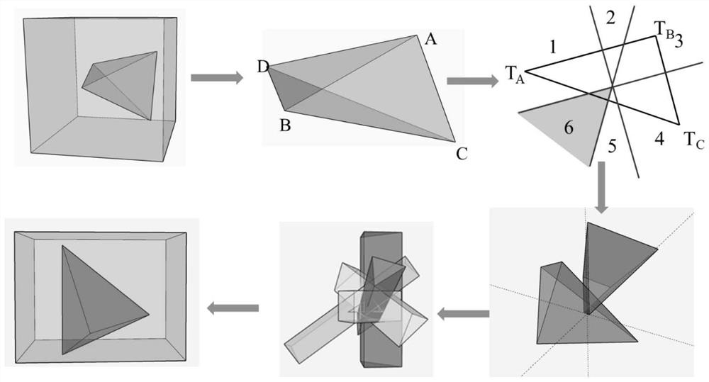
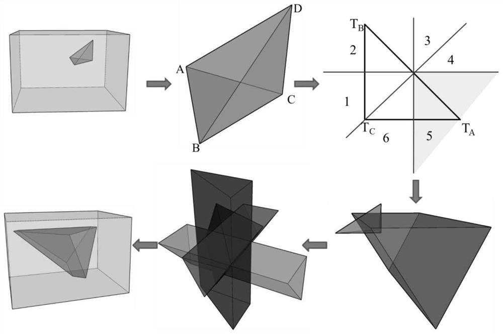
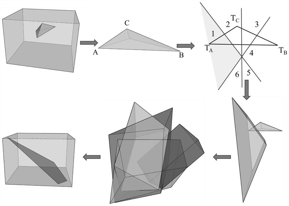
[0029] Such as Figure 1-3 A method for inversion of the heat source position in the high-temperature area of ​​the goaf in an underground coal mine is shown, including the following steps:

[0030] Step 1: Judging and selecting possible high-temperature spaces in gobs according to site conditions.

[0031] Step 2. In the selected high-temperature space, select four monitoring points A, B, C, and D with any three po...


PUM


Abstract

The invention discloses a method for retrieving the position of a heat source in a high-temperature area of ​​a goaf underground in a coal mine, and relates to the technical field of temperature monitoring of the goaf. This method firstly selects a possible high-temperature space, and measures the temperature values ​​of four monitoring points at any three points that are not collinear in the high-temperature space; The vertical line in the edge divides six areas, compares the temperature values ​​two by two, and determines the high temperature area of ​​the four surfaces; finally, the high temperature area of ​​the four surfaces extends to intersect prisms to obtain the spatial area where the heat source is located. The invention is easy to operate, not only can detect the temperature distribution of the goaf, but also can invert the heat source area according to the temperature of the measuring point, and accurately judge the heat source position of the goaf in the coal mine and other fire areas, which is beneficial to the prevention of fire fire and timely treatment after the fire occurs.

Description

technical field [0001] The invention relates to the technical field of goaf temperature monitoring, in particular to a method for inversion of the position of a heat source in a high-temperature region of an underground goaf in a coal mine. Background technique [0002] Underground coal mines, coal spontaneous combustion is one of the disasters that affect the safe recovery of working faces, and gobs are areas where coal spontaneous combustion occurs frequently. Therefore, it is very important to monitor the temperature in the goaf. [0003] Since the goaf is in a closed space, it is impossible to measure the temperature of the inner space in real time. At present, the gas detection method is often used to invert the degree of coal spontaneous combustion in gobs in field operations, and corresponding fire control measures are taken based on the inversion results. However, when using this method, due to the influence of wind flow, mining and geological occurrence in the coa...

Claims


Application Information

Patent Timeline
Patent Type & Authority Patents(China)
IPC IPC(8): G01N25/20G01N25/22
CPCG01N25/20G01N25/22
Inventor 任万兴石晶泰郭庆刘鑫杨样
Owner CHINA UNIV OF MINING & TECH
Why Eureka
Try Eureka