Vacuum wave-transparent radome with multi-layer structure

A technology of multi-layer structure and radome is applied in the field of radome to achieve the effect of improving the ability to transmit waves

Pending Publication Date: 2021-01-26
NO 54 INST OF CHINA ELECTRONICS SCI & TECH GRP
View PDF0 Cites 1 Cited by
  • Summary
  • Abstract
  • Description
  • Claims
  • Application Information

AI Technical Summary

Problems solved by technology

Although the underwater radome has similarities with it, it is exposed to the water surface to receive and transmit signals when it works, and there is no requirement for wave penetration when it is under pressure underwater. The two environments are different.

Method used


Image

  • Vacuum wave-transparent radome with multi-layer structure

Examples


Embodiment Construction

[0015] Below, the present invention will be further described in conjunction with the accompanying drawings and specific embodiments.

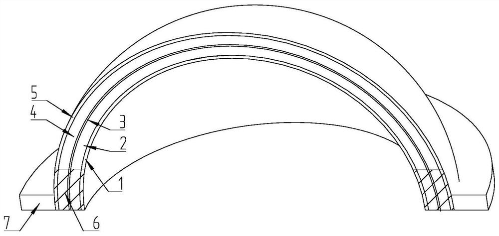
[0016] A vacuum wave-transmitting radome with a multi-layer structure, its main body is a hemispherical shell structure, including inner and outer skin layers, and the hemispherical shell structure also includes a middle skin layer and an interlayer between the skin layers; the interlayer It is a honeycomb or foam structure, and the bottom of the hemispherical shell structure is provided with a radome flange.

[0017] Further, the skin layer and the interlayer are bonded by resin or adhesive film.

[0018] Further, the connection position between the radome flange and the hemispherical shell structure is filled with glass bead foam.

[0019] Further, the material of the skin layer is quartz fiber cyanate composite material.

[0020] Below is a more specific embodiment:

[0021] Such as figure 1 As shown, a sandwich structure vacuum wave-tr...


PUM

PropertyMeasurementUnit
diameteraaaaaaaaaa
thicknessaaaaaaaaaa
thicknessaaaaaaaaaa

Abstract

The invention discloses a vacuum wave-transparent radome with a multilayer structure, and belongs to the technical field of radomes. A radome body is of a hemispherical shell structure and comprises an inner skin layer and an outer skin layer, and the hemispherical shell structure further comprises a middle skin layer and interlayers located between the skin layers. The interlayer is of a honeycomb or foam structure, and an antenna housing flange plate is arranged at the bottom of the hemispherical shell structure. The radome can be suitable for a vacuum environment, and the wave transmissionof the radome is improved under the condition that the radome is not damaged.

Description

technical field [0001] The invention relates to the technical field of radome, in particular to a vacuum wave-transmitting radome with a multi-layer structure. Background technique [0002] With the development of the astronomical field, in order to improve the imaging capability of the universe and reduce the external noise, the antenna is required to work under the low-temperature Dewar system. The main body of the system is a vacuum environment, and liquid nitrogen is used for refrigeration inside. Non-working area enclosures are usually aluminum alloys, which provide good structure and low outgassing rates. The working area requires electromagnetic waves to pass through the radome and enter the antenna to realize the reception and transmission of signals by the antenna. Therefore, it is required that the radome in the working area should not only be able to work in a low-temperature vacuum environment, but also achieve high wave transmittance. [0003] Conventional ra...

Claims


Application Information

Patent Timeline
Patent Type & Authority Applications(China)
IPC IPC(8): H01Q1/42
CPCH01Q1/422H01Q1/424
Inventor 董长胜王海东黄光耀聂小雨王豪陈超李成梁
Owner NO 54 INST OF CHINA ELECTRONICS SCI & TECH GRP
Why Eureka
Try Eureka