
Wind driven generator electricity-taking slip ring
A technology for wind turbines and electric slip rings, which is applied in the directions of motor generator connectors, circuits, collectors, etc., can solve the problem that the installation and disassembly of the slip ring for taking electricity from wind power is not convenient, the flexibility and safety are not good enough, and the installation and adjustment are not enough. Convenience and safety and other issues, to achieve the effect of enhancing wear resistance, protecting the internal structure, and prolonging the service life
- Summary
- Abstract
- Description
- Claims
- Application Information
AI Technical Summary
Problems solved by technology
Method used
Image

Examples
Embodiment
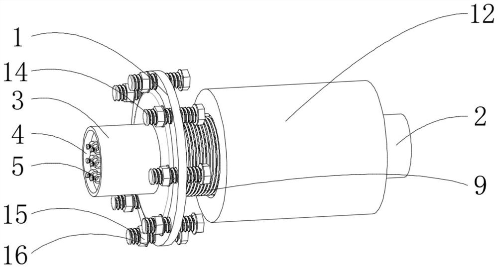
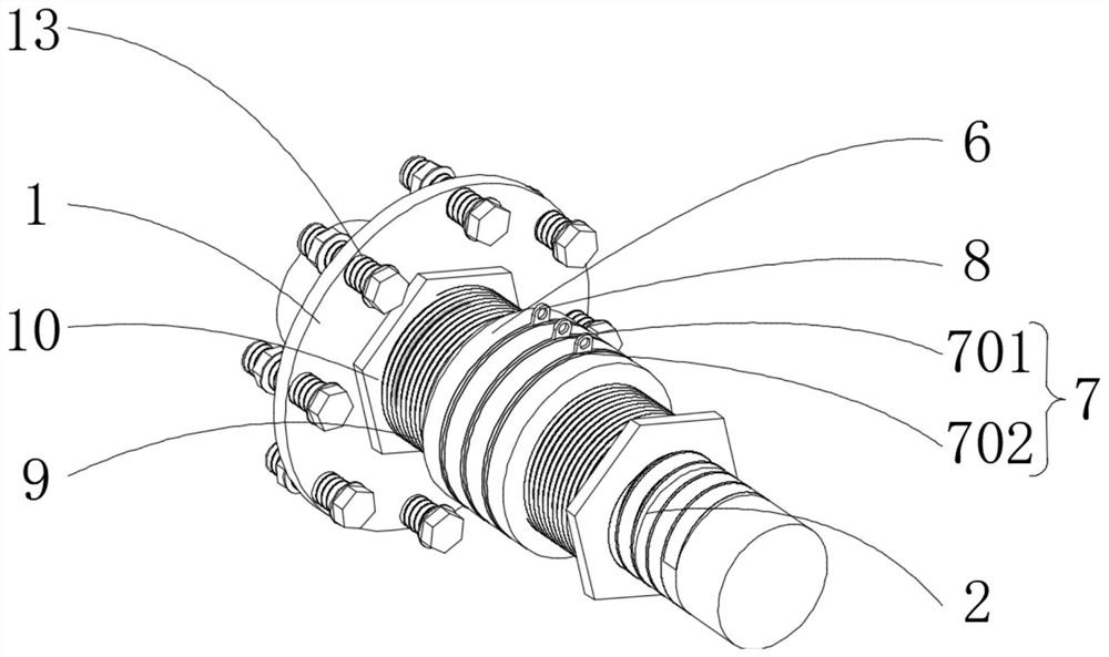
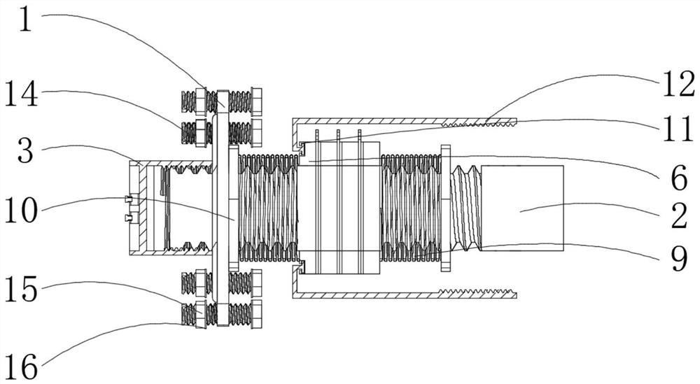
[0021] see Figure 1-3 , the present invention provides the following technical solutions: a slip ring for taking electricity from a wind power generator, including a mounting base 1, a supporting shaft 2 is movably connected to the middle of the mounting base 1, and a connecting cap 3 is fixedly connected to one side of the supporting shaft 2, and the connecting cap There is a groove 4 on one side of the groove 4, the inner bottom wall of the groove 4 is fixedly connected with the terminal 5, and the outer wall of the middle part of the support shaft 2 is movably connected with an insulating ring 6. There are four insulating rings 6, four insulating rings 6 is fixedly connected with a metal electrode piece 7, the metal electrode piece 7 includes an outer sliding piece 701 and an inner sliding piece 702, the outer wall of the outer sliding piece 701 is fixedly connected with a terminal lug 8, and one side of the insulating ring 6 is fixedly connected with a metal Spring 9, one...
PUM
 Abstract
Description
Claims
Application Information