
Drill bit for dental implantation

A drill bit and dental technology, applied in the field of dental instruments, can solve the problems of cutting capacity limitation, cutting edge size, strength reduction, jamming, etc., and achieve the effect of increasing success rate, preventing jamming, and increasing service life

Active Publication Date: 2021-01-29
CHENGDU BESMILE BIOTECH
View PDF8 Cites 2 Cited by
  • Summary
  • Abstract
  • Description
  • Claims
  • Application Information

AI Technical Summary

Problems solved by technology

After the service life is reached, the size and strength of the cutting edge will decrease, and the cutting ability will be limited
Therefore, it is necessary to cool the drill bit to improve the life of the drill bit. During the drilling process, debris will be generated, which will increase the difficulty of drilling and may cause jamming. Therefore, it is necessary to remove debris while cooling.
[0005] Moreover, when the drill bit is drilling the alveolar bone of the posterior molar, due to the size of the space in the oral cavity, the hole drilled on the alveolar bone may be inclined, and may even be caused by the drill rod being too long. Reasons why a hole in the alveolar bone cannot be successfully drilled

Method used


Image

  • Drill bit for dental implantation
  • Drill bit for dental implantation
  • Drill bit for dental implantation

Examples


Embodiment Construction

[0034] The following will clearly and completely describe the technical solutions in the embodiments of the present invention with reference to the accompanying drawings in the embodiments of the present invention. Obviously, the described embodiments are only some, not all, embodiments of the present invention. Based on the embodiments of the present invention, all other embodiments obtained by persons of ordinary skill in the art without making creative efforts belong to the protection scope of the present invention.

[0035] Unless otherwise specified, the technical means used in the implementation examples are conventional means well known to those skilled in the art.

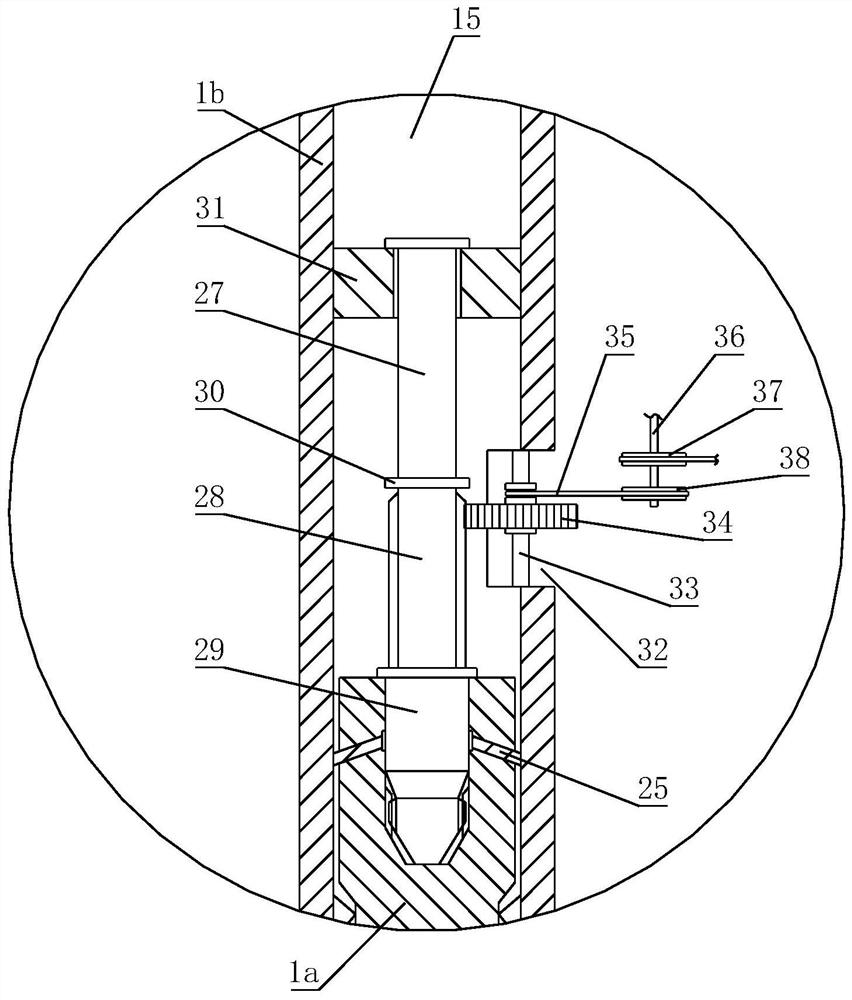
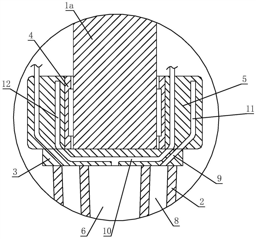
[0036] refer to Figure 1-Figure 12 , the invention discloses a drill bit for dental implantation, comprising a drill rod 1 and a drill bit 2 fixedly connected to the drill rod 1, the drill bit 2 and the drill rod 1 are fixed by a substrate 3, located above the substrate 3 and on the drill rod 1 The bearin...


PUM


Abstract

The invention relates to the technical field of dental instruments, in particular to a drill bit for dental implantation. According to the specific technical scheme, the drill bit for dental implantation comprises a drill bit body and a drill rod which are fixed through a base plate, the drill rod is sleeved with a bearing, a base table is fixed to the outer ring of the bearing, a water storage cavity is formed in the axis of the drill bit body, a water outlet channel communicated with the water storage cavity is formed in the water storage cavity, and a chip suction cavity is formed in the drill bit body around the water storage cavity. A plurality of chip suction holes communicated with the chip suction cavity are formed in the side wall of the drill bit; a plurality of annular chip suction holes communicated with the chip suction cavity and a plurality of water inlet channels communicated with the water storage cavity are formed in the base plate, an annular chip suction groove communicated with the annular chip suction holes and an annular water inlet groove communicated with the water inlet channels are formed in the base table, and an air port and a water inlet are formed inthe annular chip suction groove and the annular water inlet groove respectively. The air port and the water inlet are connected with an air pump and a water pump through pipelines respectively. In theworking process of the drill bit, cooling and chip removal can be conducted on the drill bit at the same time.

Description

technical field [0001] The invention relates to the technical field of dental instruments, in particular to a drill bit for dental implantation. Background technique [0002] The existing drill bits for dental implants are made of stainless steel or hard alloy materials. They are connected to the mobile phone for implantation through the handle. The high-speed rotation of the mobile phone drives the drill bit to rotate. The working part directly acts on the alveolar bone of the human body. Drill holes on the alveolar bone in the same way. After the drilling is completed, the mobile phone is reversed and withdrawn from the drill bit. The size of the drill bit matches the diameter of the dental implant, and the operator selects the matching drill bit according to the size of the implant to be used. [0003] Drills for planting are divided into positioning drills, pilot drills, pilot drills, reaming drills and forming drills. The material is stainless steel, and the most frequ...

Claims


Application Information

Patent Timeline
Patent Type & Authority Applications(China)
IPC IPC(8): A61C3/02
CPCA61C3/02
Inventor 冯崇敬王昌健杨维刘俊平鄢新章刘谋山
Owner CHENGDU BESMILE BIOTECH
Learn More