
Mine field dust removal purifier based on environmental protection engineering

A technology for environmental protection engineering and purifiers, applied in chemical instruments and methods, dust-proofing, mining equipment, etc., can solve the problems of polluting the environment, inconvenient use of water adjustment, and inability to rationally use water resources.

Inactive Publication Date: 2021-01-29
金岑
View PDF4 Cites 4 Cited by
  • Summary
  • Abstract
  • Description
  • Claims
  • Application Information

AI Technical Summary

Problems solved by technology

[0005] In order to solve the above-mentioned technical problems, the present invention provides a mine dust removal purifier based on environmental protection engineering, to solve the problem that when the existing dust removal purifier is in use, it is inconvenient to use spray dust removal to adjust the water volume, and it is difficult to carry out dust removal in the mine field. When it is used, the amount of water cannot be adjusted in time according to the amount of dust content. Excessive water flow causes waste of resources. When the existing dust removal purifier is in use, the water used for wet dust removal will be discharged directly, which is a waste of water resources. It also pollutes the environment and cannot use water resources reasonably

Method used


Image

  • Mine field dust removal purifier based on environmental protection engineering
  • Mine field dust removal purifier based on environmental protection engineering
  • Mine field dust removal purifier based on environmental protection engineering

Examples


Embodiment

[0034] as attached figure 1 to attach Figure 8 Shown:

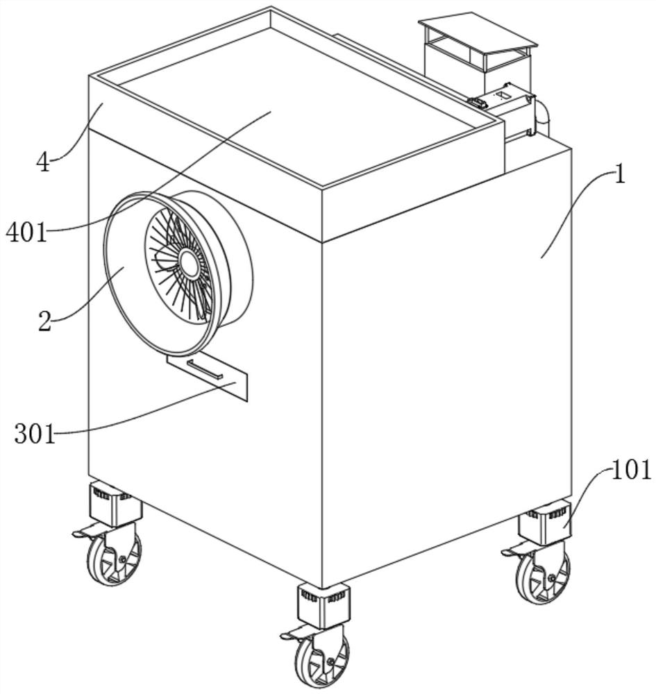
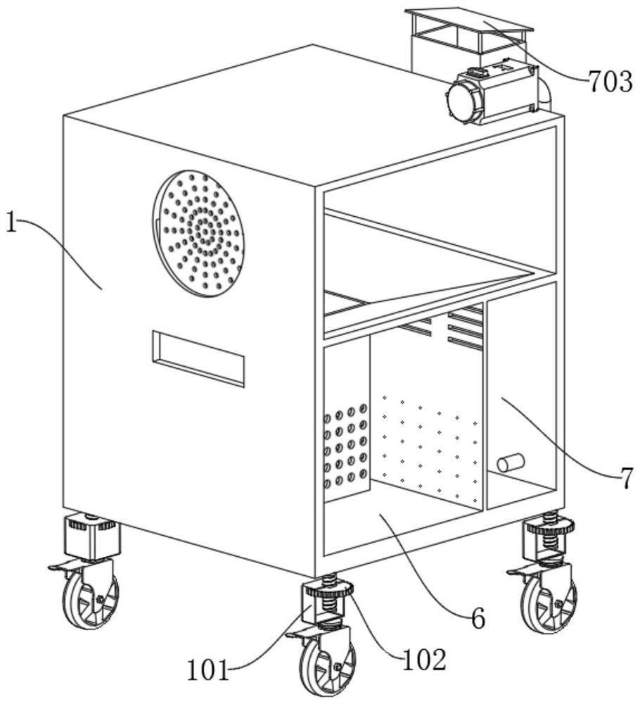
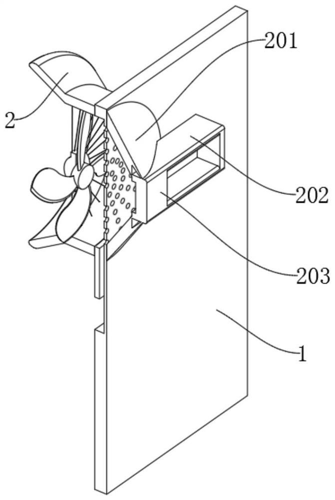
[0035] The present invention provides a mine dust removal purifier based on environmental protection engineering, comprising a main body 1, an air inlet 2, a vertical groove 3, a water tank 4, a horizontal plate 5, a water tank 6 and a water storage tank 7, the main body 1 is a rectangular structure, and A water pump is installed on the top of the main body 1; an impeller is installed inside the air inlet 2, and the air inlet 2 is set on the side of the main body 1, and the inner plate 201 inside the air inlet 2 is set on the inside of the main body 1; the vertical groove 3 is set on the main body 1, and the rotating rod 301 on the top of the vertical groove 3 is set at the inner end of the impeller inside the air inlet 2; the water tank 4 is installed on the top of the main body 1, and the water outlet part 402 at the bottom of the water tank 4 is installed on the inner top of the main body 1; The water tank 6 is loca...


PUM


Abstract

The invention provides a mine field dust removal purifier based on environmental protection engineering, relates to the technical field of environmental protection engineering equipment, and aims at solving the problems that when an existing dust removal purifier is used, the water amount cannot be adjusted in time according to the dust content, and excessive water flow causes resource waste. Thepurifier comprises a main body, a transverse plate and water storage pool. A vertical groove is formed in the side face of the main body, and a rotating rod at the top of the vertical groove is arranged at the inner end of the impeller in an air inlet. A water tank is mounted at the top of the main body. The side surface of a water guide plate at the top of the water tank is connected with the inner side of the main body. A baffle on the side surface of the transverse plate is mounted on the side surface of a water outlet part. A push plate on the side surface of the transverse plate is mounted on the side surface of an inner plate through a spring. The water storage pool is arranged in the main body, and an air duct on the side surface of the water storage pool is arranged on the side surface of the main body. When dust removal is carried out on a mine field, the water volume can be adjusted through the transverse plate according to the wind volume, and water resources are reasonablyutilized through the water storage pool, so that the water resources are recycled.

Description

technical field [0001] The invention belongs to the technical field of environmental protection engineering equipment, and more specifically relates to a mine dust collector based on environmental protection engineering. Background technique [0002] During the mining process, a large amount of dust is produced due to processing and crushing, which may cause potential harm to the surrounding environment and the human body. Therefore, it cannot be directly discharged into the atmosphere. It must be subjected to dust removal treatment. In the mine, dust removal purifiers are used to purify the air, reducing it to hazard to personnel. [0003] For example, the application number: CN201510046762.X relates to a dust removal purifier, which includes a clean air purification chamber, a box body and an ash hopper which are sequentially connected from top to bottom. The air outlets are connected, and a cloth bag with a keel is installed in the box. The upper end of the bag is connec...

Claims


Application Information

Patent Timeline
Patent Type & Authority Applications(China)
IPC IPC(8): B01D50/00B01D47/06B01D46/10E21F5/04B01D29/03
CPCB01D47/06B01D46/10B01D29/03E21F5/04B01D2247/04B01D50/60
Inventor 金岑
Owner 金岑
Learn More