Sub-motor-driven wire drawing machine

A wire drawing machine and separate motor technology, which is applied in the direction of wire drawing dies, transmission boxes, mechanical equipment, etc., can solve the problems of high maintenance cost, large consumption of lubricating oil, high manufacturing cost, etc., and achieve the effect of reliable sealing and isolation

Pending Publication Date: 2021-01-29
JIANGSU HONTA MACHINERY
View PDF0 Cites 0 Cited by
  • Summary
  • Abstract
  • Description
  • Claims
  • Application Information

AI Technical Summary

Problems solved by technology

[0003] The above-mentioned wire drawing machine with the conventional structure has a large manufacturing workload and requires high manufacturing precision of the gear transmission pair. It needs to be equipped with a corresponding transmission box, lubrication, cooling device, and a sealing device with excellent performance between the transmission box body and the wire drawing wheel shaft. The manufacturing cost High, and a large amount of lubricating oil is consumed during the use of the wire drawing machine. The maintenance requirements of the gear transmission pair and the supporting lubrication devic

Method used


Image

  • Sub-motor-driven wire drawing machine
  • Sub-motor-driven wire drawing machine
  • Sub-motor-driven wire drawing machine

Examples


Embodiment Construction

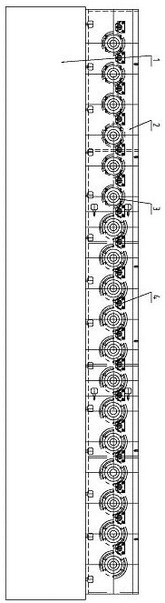
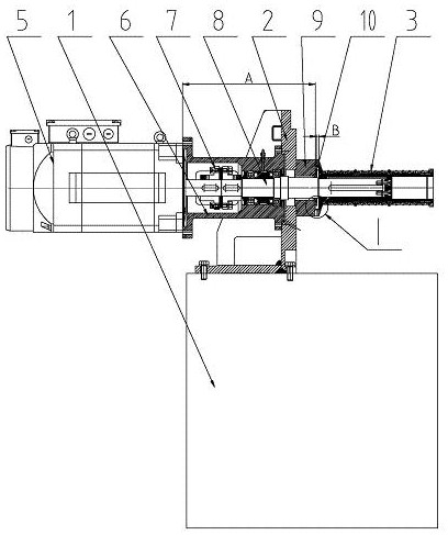
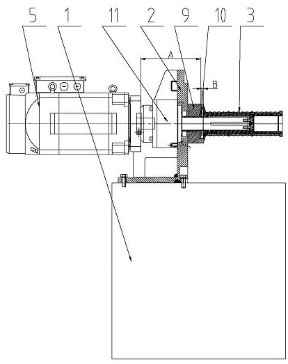
[0024] exist figure 1 with figure 2 In the motor-driven wire drawing machine shown, the machine base 1 is in the shape of a cuboid box, which is the basic supporting member of the wire drawing machine. The vertical plate 2 is fixedly connected to the machine base 1, and the cross section of the vertical plate 2 is square-shaped. , its bottom surface is fixedly connected with the machine base 1, and the vertical plate 2 can be an integral structure, but it is preferably formed by splicing and combining a plurality of discrete plates along the length direction through connecting bolts, and three or four groups are arranged on each discrete plate Or five or six or seven wire drawing assemblies form a modular assembly, which can be easily combined into wire drawing machines with different numbers of wire drawing wheels. A wire drawing die assembly is arranged between the two wire drawing wheels 3, and the wire drawing die assembly includes a wire drawing die and a wire drawing d...


PUM


Abstract

The invention discloses a sub-motor-driven wire drawing machine. The sub-motor-driven wire drawing machine comprises a machine base, wire drawing wheels and wire drawing wheel driving motors, each wire drawing wheel corresponds to one wire drawing wheel driving motor, a vertical plate is fixedly connected to the machine base, the wire drawing wheel driving motors and the wire drawing wheels are arranged on the two sides of the vertical plate respectively, the distance A between the installation end face of each wire drawing wheel driving motor and the end face of the wire drawing wheel opposite to the wire drawing wheel driving motor ranges from 500 mm to 100 mm, the wire drawing wheel driving motors are fixedly connected to one side of the vertical plate, and the wire drawing wheels are connected with output shafts of the corresponding wire drawing wheel driving motors; and wire drawing sealing seats corresponding to the wire drawing wheels are arranged on the vertical plate, the endfaces of the inner sides of the wire drawing wheels are embedded in the wire drawing sealing seats, sealing rings are arranged between inner holes of the wire drawing sealing seats and installation shafts corresponding to the wire drawing wheels, and the distance B between the sealing rings and the opposite end faces of the wire drawing wheels ranges from 2 mm to 20 mm. The sub-motor-driven wire drawing machine can meet the production process requirements of wire cores of different specifications and materials, and is high in production efficiency, simple in structure and convenient to use andmaintain.

Description

technical field [0001] The invention relates to a wire and cable production equipment, in particular to a wire drawing machine for manufacturing wire and cable core materials. Background technique [0002] The wire and cable core material is thinned to the required specifications by the wire drawing machine. During the wire drawing process, the wire passes around several wire drawing wheels whose surface speed gradually increases, and the wire drawing die between adjacent wire drawing wheels Under the action of the wire, the wire is gradually stretched and thinned, and finally reaches the required specifications. In the wire drawing machine of the existing structure, the wire drawing wheel is rotatably supported on the wire drawing transmission box and is driven to rotate by the wire drawing drive motor through the gears in the wire drawing transmission box. The rotational speed difference between the wheels is determined by the transmission ratio of the gears. [0003] Th...

Claims


Application Information

Patent Timeline
IPC IPC(8): B21C1/04B21C1/12B21C1/14B21C3/12B21C9/00F16H57/025F16H57/02F16J15/16
CPCB21C1/04B21C1/12B21C1/14B21C3/12B21C9/00F16H57/02F16H57/025F16H2057/02034F16J15/16
Inventor 谭礼春孟令云刘倩
Owner JIANGSU HONTA MACHINERY
Why Eureka
Try Eureka