
Special sand tire and wear resistance detection device thereof

A tire and sand technology, which is applied in the field of special sand tires and their wear resistance detection devices, can solve the problems such as the inability to effectively gather sand particles, the decline of straight-forward traction performance, and the impact on tire performance.

Active Publication Date: 2021-01-29
ZHAOQING JUNHONG CO LTD
View PDF17 Cites 2 Cited by
  • Summary
  • Abstract
  • Description
  • Claims
  • Application Information

AI Technical Summary

Problems solved by technology

The tire with this kind of tread pattern structure can quickly cut the pattern block into the sand to improve the traction performance, but when turning on the sand, the ground contact area of ​​the tire is low and the tread transverse grooves are large, so it is easy to slip when turning. At the same time, when the tires are driving straight ahead, because the first ground contact end of the tires is a smooth surface, it is also prone to sand particles that cannot be effectively assembled, resulting in a decrease in straight-forward traction performance. Problems, due to the constraints of its structural characteristics affect the performance of tires

Method used


Image

  • Special sand tire and wear resistance detection device thereof
  • Special sand tire and wear resistance detection device thereof
  • Special sand tire and wear resistance detection device thereof

Examples


Embodiment

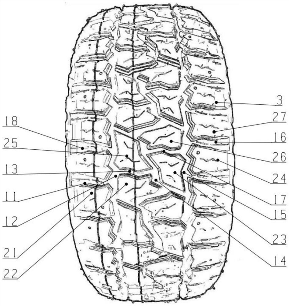
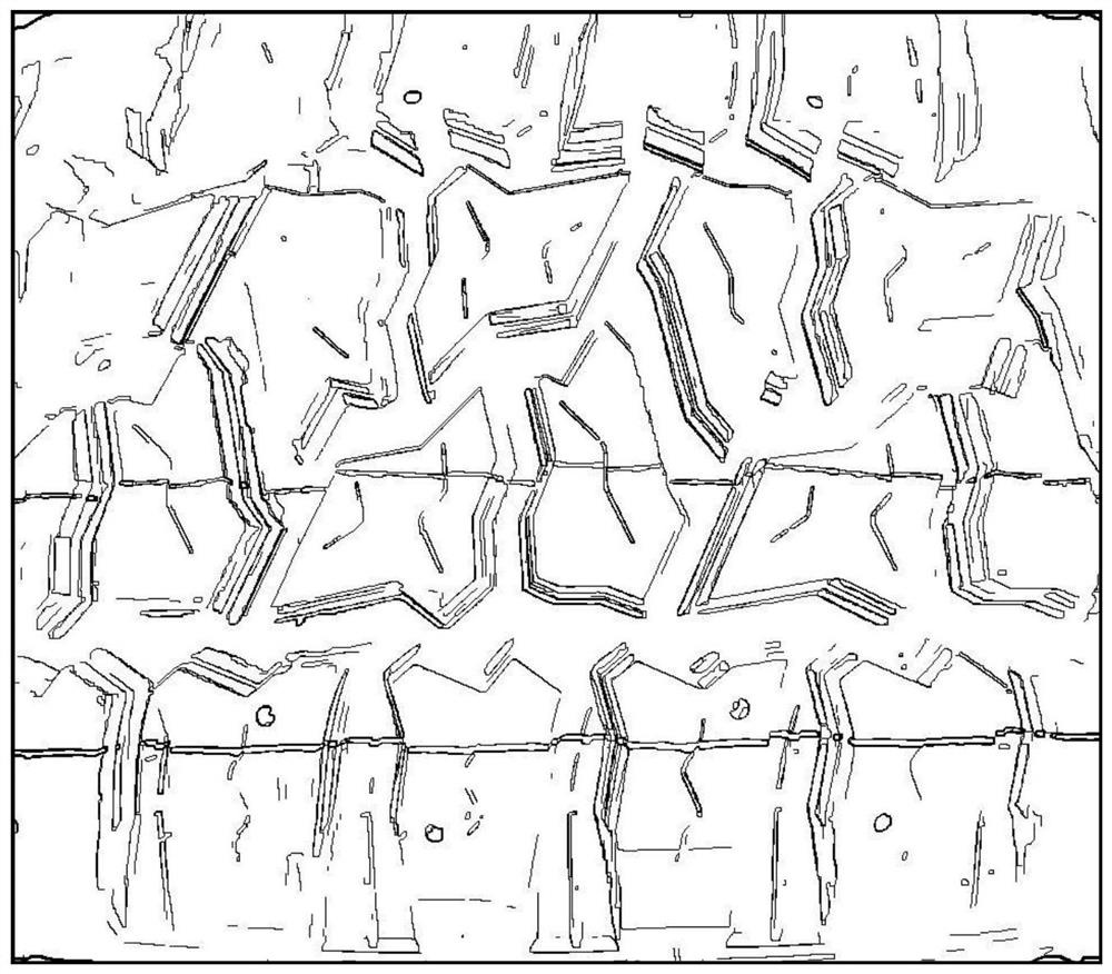
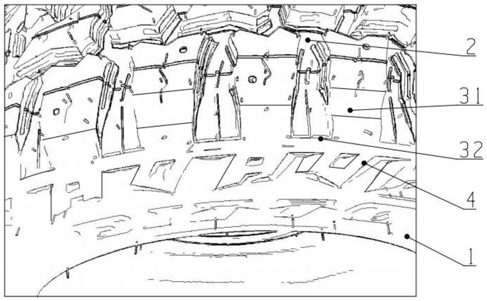
[0043] The present invention will be further described below in conjunction with the accompanying drawings.

[0044] Such as Figure 1-3 As shown, the special sand tire provided in this embodiment includes:

[0045]Carcass 1, the outer ring of the carcass 1 is formed with a tread 2, the edge of the tread 2 is formed with a tire shoulder 3, and several pattern blocks are arranged on the tread 2 and the tire shoulder 3, and the pattern blocks Arranged symmetrically and staggered on the left and right sides of the circumferential axis of the tread 2, the pattern blocks include a group of tread pattern blocks arranged on the tread 2 and distributed along the tire circumferential direction, and arranged on the shoulder 3 along the tire The shoulder pattern block groups distributed in the circumferential direction, the ends of the shoulder pattern block groups extend toward the sidewall to form the under-shoulder pattern blocks 4 .

[0046] Working principle of the present inventi...


PUM


Abstract

The invention discloses a special sand tire and wear resistance detection device thereof. The special sand tire comprises a tire body, wherein a tire tread is formed on an outer ring of the tire body,a tire shoulder is formed on an edge of the tire tread, a plurality of pattern blocks are arranged on the tire tread and the tire shoulder, and the pattern blocks are symmetrically arranged on the left side and the right side of the circumferential axis of the tire tread in a staggered mode; each pattern block comprises a tread pattern block group arranged on the tread and distributed along the circumferential direction of the tire, and a tire shoulder pattern block group arranged on the tire shoulder and distributed along the circumferential direction of the tire, and the tail end of the tire shoulder pattern block group extends towards the tire side to form an under-shoulder pattern block. According to the special sand tire, a computer model is established to simulate the size and shapeof a grounding mark, the grounding pressure and distribution condition, and the contact condition of a pattern and a soft pavement of a tire in soft lands such as deserts, sand lands, beaches and thelike so as to design a pattern groove with a U-shaped structure and an undirected blocky pattern block; the passing rate of the special sand tire on a soft road surface is increased, the functions ofwater drainage, mud discharge, sand discharge and the like are improved, stability and the quick turning performance of a vehicle are improved, and meanwhile the control performance of the tire is improved.

Description

technical field [0001] The invention relates to the technical field of vehicle tires, in particular to a special sand tire and a wear-resistant detection device thereof. Background technique [0002] When all-terrain tires are driving on sand dune terrain, because the sand particles are relatively soft, it is difficult for the tires to gather to provide corresponding traction, resulting in poor handling of the tires, especially in the front wheels. light phenomenon. The tread block traverses the entire tread width, and the shoulders are often designed with a curved surface in order to make the tire exert better traction. The tire with this kind of tread pattern structure can quickly cut the pattern block into the sand to improve the traction performance, but when turning on the sand, the ground contact area of ​​the tire is low and the tread transverse grooves are large, so it is easy to slip when turning. At the same time, when the tires are driving straight ahead, becaus...

Claims


Application Information

Patent Timeline
IPC IPC(8): B60C11/03B60C11/12B60C11/13B60C11/01G01M17/02
CPCB60C11/01B60C11/03B60C11/1204B60C11/1259B60C11/1272B60C11/13B60C2011/013B60C2011/0337G01M17/02G01M17/021
Inventor 林丛海张碧俊丁金刚吉年康覃进明
Owner ZHAOQING JUNHONG CO LTD
Learn More