Supercharge Your Innovation With Domain-Expert AI Agents!

Protection device of new energy charging pile

A protective device and charging pile technology, applied in charging stations, lighting devices, lighting devices, etc., can solve the problems of easy damage to charging cables, easy electric shock, and reduced service life of equipment, so as to avoid damage, enhance safety, The effect of enhancing the service life

Pending Publication Date: 2021-01-29
株洲瑞尔泰机电科技有限公司
View PDF6 Cites 0 Cited by
  • Summary
  • Abstract
  • Description
  • Claims
  • Application Information

AI Technical Summary

Problems solved by technology

[0003] The charging pile is inseparable from the use of new energy vehicles. The function of the charging pile is similar to that of the fuel dispenser in the gas station, but the existing charging cables are exposed outside the charging pile. The charging cables of the charging pile are exposed outside for a long time. Wind and sun are prone to damage, causing people not only to be prone to the risk of electric shock when using it, but also greatly reducing the service life of the equipment. Therefore, in view of the above status quo, it is urgent to develop a protective device for new energy charging piles. Deficiencies in Current Practical Applications

Method used


Image

  • Protection device of new energy charging pile
  • Protection device of new energy charging pile
  • Protection device of new energy charging pile

Examples


Embodiment 1

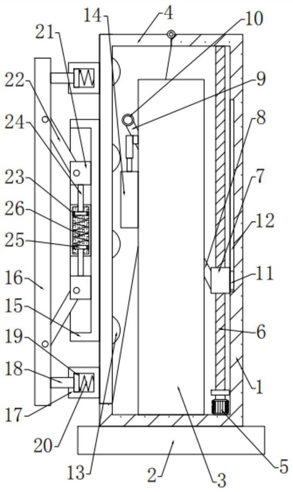
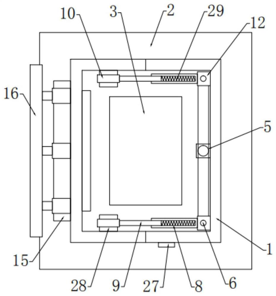
[0026] see Figure 1-4 In an embodiment of the present invention, a protective device for a new energy charging pile includes a base 2, the top of the base 2 is fixedly connected with a fixed frame 1, and the inner side of the fixed frame 1 is bolt-connected with a charging pile 3, the The outer side of the charging pile 3 is fixedly connected with a connection box 14 for receiving and releasing cables, and the top of the fixed frame 1 is hingedly provided with a protective cover 4, and the protective cover 4 is connected to the driving mechanism arranged inside the fixed frame 1 through a transmission mechanism , the outer side of the protective cover 4 is provided with a buffer mechanism.

Embodiment 2

[0028] In this embodiment, the driving mechanism includes a first motor 5 that is bolted to the inner bottom of the fixed frame 1, and the front and rear sides of the first motor 5 are provided with threaded rods 6 that are rotatably connected to the fixed frame 1. The outside of the threaded rod 6 and the output end of the first motor 5 are fixedly connected with pulleys, the pulleys are connected by a belt, and the outside of the threaded rod 6 is bolted to be provided with a movable block 7 that is slidably connected to the fixed frame 1, The movable block 7 is connected with the protective cover 3 through a transmission mechanism.

[0029] In this embodiment, a guide block 11 is fixedly connected to the outer side of the movable block 7 , and the guide block 11 is slidably connected to a guide groove 12 provided on the inner side of the fixed frame 1 .

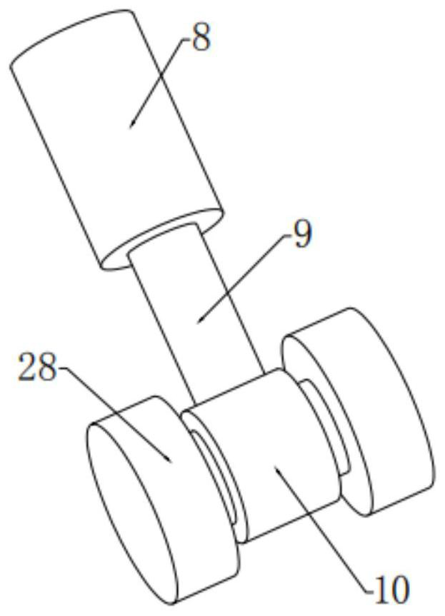
[0030] In this embodiment, the transmission mechanism includes a fixed rod 8 fixedly connected to the outside of the con...


PUM


Abstract

The invention relates to the technical field of charging piles, in particular to a protection device of a new energy charging pile. The device comprises a base, a fixing frame is fixedly connected tothe top of the base, a charging pile is connected to the inner side of the fixing frame through bolts, a connecting box fixedly connected to the outer side of the charging pile and used for winding and unwinding a cable, and a protection cover is hinged to the top of the fixing frame. The protection cover is connected with a driving mechanism arranged on the inner side of the fixing frame througha transmission mechanism, and a buffer mechanism is arranged on the outer side of the protection cover. The protection cover can be opened and closed by arranging the driving mechanism and the transmission mechanism, so that the charging cable is prevented from being damaged due to long-term exposure to the outside and wind and sun, and the service life of the equipment is prolonged; and by arranging the connecting box, the cable can be wound and unwound, so that the situation that opening and closing of the protectiion cover are affected due to the fact that the cable is exposed to the outerside of the device is avoided, and meanwhile, the cable can be further protected.

Description

technical field [0001] The invention relates to the technical field of charging piles, in particular to a protective device for new energy charging piles. Background technique [0002] With the deepening of the global energy crisis, the depletion of oil resources and the increasing harm of air pollution and global temperature rise, governments and automobile companies generally recognize that energy saving and emission reduction are the future development direction of automobile technology, and the development of new energy vehicles will be The best way to solve these two problems. New energy vehicles refer to vehicles that use unconventional vehicle fuels as power sources, integrate advanced technologies in vehicle power control and drive, and form vehicles with advanced technical principles, new technologies, and new structures. New energy vehicles include four types of hybrid electric vehicles, pure electric vehicles, fuel cell electric vehicles, and other new energy veh...

Claims


Application Information

Patent Timeline
IPC IPC(8): B60L53/31B60L53/30F21S8/00F21V33/00
CPCB60L53/31B60L53/30F21S8/00F21V33/00Y02T10/70Y02T10/7072Y02T90/12
Inventor 杨又伦曹剑覃远福刘建华
Owner 株洲瑞尔泰机电科技有限公司
Features
  • R&D
  • Intellectual Property
  • Life Sciences
  • Materials
  • Tech Scout
  • Unparalleled Data Quality
  • Higher Quality Content
  • 60% Fewer Hallucinations
Learn More