

Energy-saving and environment-friendly collecting device for kitchen waste
An energy-saving and environmental-friendly collection device technology, which is applied in the direction of garbage collection, trash cans, applications, etc., can solve the problems of lack of better automation and insufficient smoothness of grinding, and achieve the effect of improving practicability and reducing labor intensity
- Summary
- Abstract
- Description
- Claims
- Application Information
AI Technical Summary
Problems solved by technology
Method used
Image

Examples
Embodiment 1
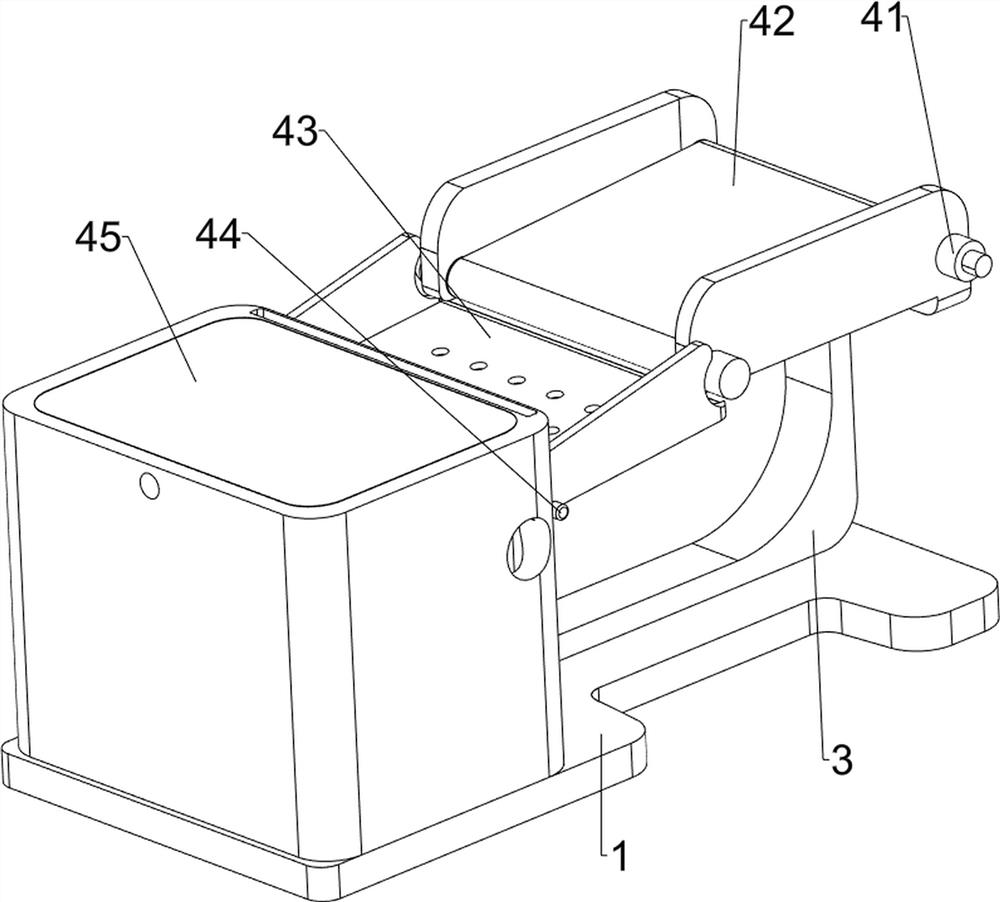
[0076] An energy-saving and environment-friendly collection device for kitchen waste, such as figure 1 As shown, it includes a base 1, a first fixed block 2, a bracket 3, a screening mechanism 4 and a pulling mechanism 5, the first fixed block 2 is welded on the front side of the top of the base 1, the bracket 3 is fixed in the middle of the top of the base 1, and the base 1 A screening mechanism 4 is arranged on the top and the support 3, and a pulling mechanism 5 is installed on the screening mechanism 4, and the pulling mechanism 5 contacts and cooperates with the screening mechanism 4.
[0077] When a worker needs to collect food waste, the worker needs to pour an appropriate amount of food waste onto the screening mechanism 4, and then the worker needs to control the rotation of the screening mechanism 4, and the rotation of the screening mechanism 4 will drive the food waste to move to the rear side for screening Mechanism 4 can separate the oil and water in the food was...
Embodiment 2
[0079] In a preferred embodiment of the present invention, as figure 2 As shown, the screening mechanism 4 includes a drum 41, a conveyor belt 42, a screen frame 43, a first rotating shaft 44 and a collection frame 45, and the upper part of the support 3 is symmetrically rotated forward and backward and is provided with a drum 41, and the front and back two drums 41 are connected with a conveyor belt 42 in the middle. A collecting frame 45 is fixedly connected to the rear side of the top of the base 1, and the upper part of the front side of the collecting frame 45 is rotatably provided with a first rotating shaft 44, and a screen frame 43 is fixedly connected to the first rotating shaft 44, and the front end of the screen frame 43 is in contact with the drum 41 on the rear side Cooperate.
[0080] Workers first need to pour the kitchen waste onto the conveyor belt 42. When the kitchen waste is on the conveyor belt 42, the worker needs to manually rotate the drum 41. The rota...
Embodiment 3
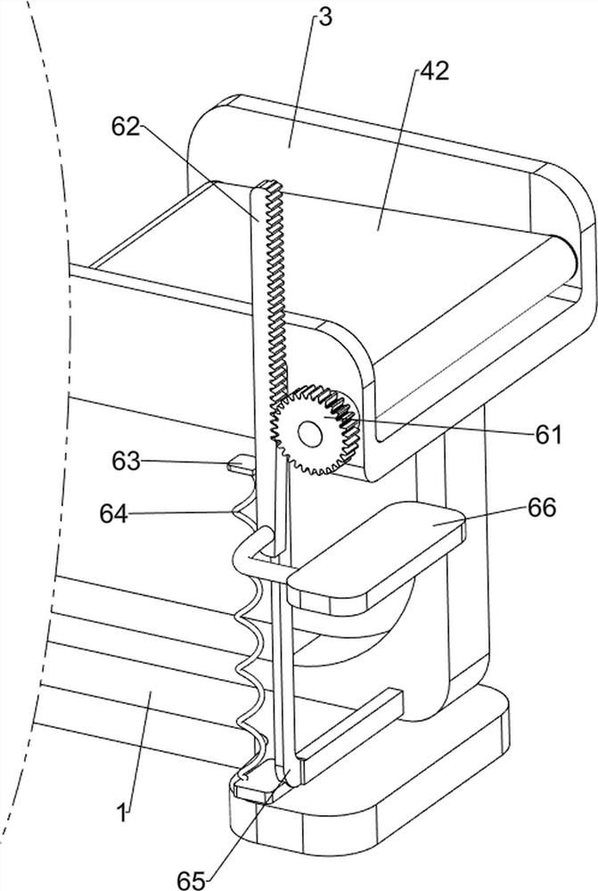
[0082] In a preferred embodiment of the present invention, as figure 1 and Figure 3-Figure 8 As shown, the pulling mechanism 5 includes a first gear 51, a second gear 52, a second rotating shaft 53, a first rack 54, a fixed frame 55, a first sliding column 56, a first spring 57 and a baffle plate 58, the rear side The right end of the drum 41 is equipped with a first gear 51, and the front side of the right part of the screen frame 43 is rotatably provided with a second rotating shaft 53. The second rotating shaft 53 is equipped with a second gear 52, and the second gear 52 is in contact with the first gear 51. , the top of the front side of the collection frame 45 is welded with a fixed frame 55, and the symmetrical sliding type on the left and right sides of the fixed frame 55 top is provided with a first sliding column 56, and a baffle plate 58 is connected between the bottom ends of the two first sliding columns 56, and the baffle plate 58 is slidably connected with the ...
PUM
 Abstract
Description
Claims
Application Information