Eureka AIR delivers breakthrough ideas for toughest innovation challenges, trusted by R&D personnel around the world.

Vacuum well equipment cavity ventilation and pollution discharge device

A sewage discharge device and vacuum technology, which is applied in the direction of sewage discharge, water supply device, drainage structures, etc., can solve the problems that the equipment in the vacuum well is prone to paralysis, cannot effectively solve the problems of sewage detection and sewage discharge above the well cover, and achieve the effect of reducing the service life

Pending Publication Date: 2021-01-29
QINGHUAN TUODA (SUZHOU) ENVIRONMENTAL TECH CO LTD
View PDF6 Cites 0 Cited by
  • Summary
  • Abstract
  • Description
  • Claims
  • Application Information

AI Technical Summary

Problems solved by technology

[0022] The purpose of the present invention is to provide a vacuum well equipment cavity ventilation and sewage discharge device to solve the problem that in the prior art, in the well cover ventilation type vacuum well system, the detection and discharge of sewage above the well cover cannot be effectively solved, which causes the equipment in the vacuum well to work easily. problem of paralysis

Method used


Image

  • Vacuum well equipment cavity ventilation and pollution discharge device
  • Vacuum well equipment cavity ventilation and pollution discharge device
  • Vacuum well equipment cavity ventilation and pollution discharge device

Examples


Embodiment Construction

[0061] Below in conjunction with specific embodiment, content of the present invention is described in further detail:

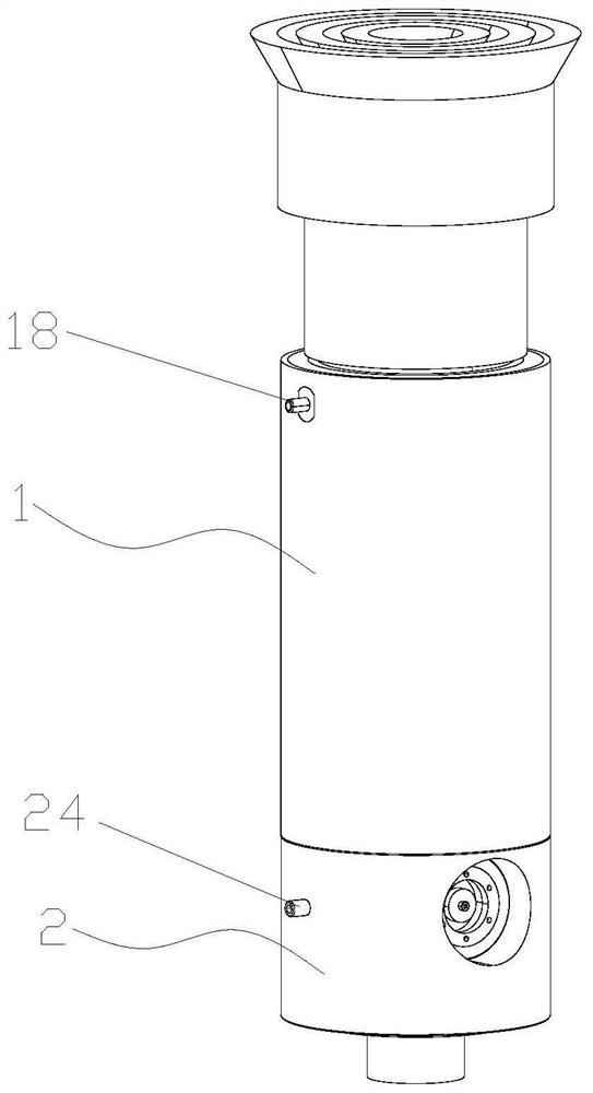
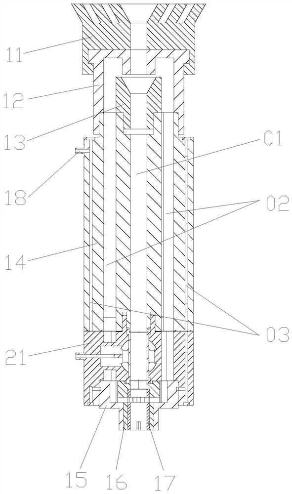
[0062] Such as figure 1 As shown, a vacuum well equipment cavity ventilation and sewage discharge device includes a cylinder 1 and a pinch valve 2 connected to the cylinder 1 and used to realize the internal opening and closing of the cylinder 1; figure 2As shown, the main channel 01, the side channel 02 connected to the upper and lower ends of the main channel 01, and the sensor pipeline 03 connected to the lower end of the side channel 02 are jointly formed inside the cylinder body 1 and the pinch valve 2; 1 The outer wall is provided with a sensor interface 18 connected with the sensor pipeline 03; the pinch valve 2 is coaxially arranged with the cylinder body 1, and is used to control the main channel 01 on and off.

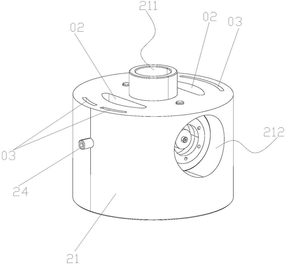
[0063] Such as image 3 , Figure 4 and Figure 5 As shown, the pinch valve 2 includes a valve body 21, a hose 22 arranged inside the...


PUM


Abstract

The invention relates to a vacuum well equipment cavity ventilation and pollution discharge device. The vacuum well equipment cavity ventilation and pollution discharge device comprises a barrel and apipe clamp valve connected with the barrel and used for achieving opening and closing of the interior of the barrel, wherein a main runner, side runners communicating with the upper end and the lowerend of the main runner and sensor pipelines communicating with the lower ends of the side runners are jointly formed in the barrel and the pipe clamp valve; a sensor interface communicating with thecorresponding sensor pipeline is arranged on the outer wall of the barrel; and the pipe clamp valve and the barrel are coaxially arranged, and the pipe clamp valve is used for controlling opening andclosing of the main runner. The device is applied to a well lid ventilation type vacuum well, reasonable ventilation in the vacuum well can be guaranteed, and the problems of detection and pollution discharge of sewage on a well lid can be solved, so that different weather conditions can be met, and the problems that under the severe weather condition, a large amount of accumulated water flows into the vacuum well, so that internal equipment works uninterruptedly, the energy consumption is increased, and the service life is shortened are solved.

Description

technical field [0001] The invention relates to the technical field of vacuum sewage continuous collection, temporary storage and periodic delivery system. The vacuum sewage continuous collection, temporary storage and periodic delivery system is a vacuum well system, which has temporary sewage collection using vacuum sewage valve for periodic sewage discharge tank, and can transport the sewage in its sewage collection tank to the downstream vacuum collection pipeline network, which is controlled by the control device of the differential pressure drive control method. The upper end of the vacuum well is provided with a sealed well cover with a vent. It is convenient to realize the ventilation function of the internal equipment, but while ensuring the ventilation function, it is necessary to ensure that the vacuum well can achieve automatic detection and automatic sewage discharge under harsh environmental conditions. Therefore, the present invention particularly relates to a va...

Claims


Application Information

Patent Timeline
Patent Type & Authority Applications(China)
IPC IPC(8): E03F1/00E03F5/04E03F5/08E03F7/02E01C11/26
CPCE01C11/26E03F1/00E03F1/006E03F5/0401E03F5/041E03F5/08E03F7/02E03F2201/20
Inventor 崔利兴邓永峰
Owner QINGHUAN TUODA (SUZHOU) ENVIRONMENTAL TECH CO LTD
Why Eureka
Eureka Blog
Learn More