Device and method for quickly giving azimuth angle of drill hole

A positioning device and azimuth angle technology, applied in the field of drilling, can solve the problems of inaccurate drilling and centerline setting, affecting the accuracy of compass, inaccurate drilling setting, etc., so as to achieve fast and convenient installation and high work efficiency. , the effect of small cumulative error

Pending Publication Date: 2021-01-29
PANJIANG COAL & ELECTRICITY GROUP INSITUTE OF COAL MINING DESIGN +1
View PDF0 Cites 0 Cited by
  • Summary
  • Abstract
  • Description
  • Claims
  • Application Information

AI Technical Summary

Problems solved by technology

[0003] However, in the process of using the existing technology, it is found that because the excavation face often has a lot of iron objects, and the iron objects are magnetic, which will seriously affect the accuracy of the compass, resulting in inaccurate setting of the horizontal angle between the drill hole and the center line, making the drilling accuracy The azimuth angle is finally given inaccurately

Method used


Image

  • Device and method for quickly giving azimuth angle of drill hole
  • Device and method for quickly giving azimuth angle of drill hole
  • Device and method for quickly giving azimuth angle of drill hole

Examples


Embodiment 1

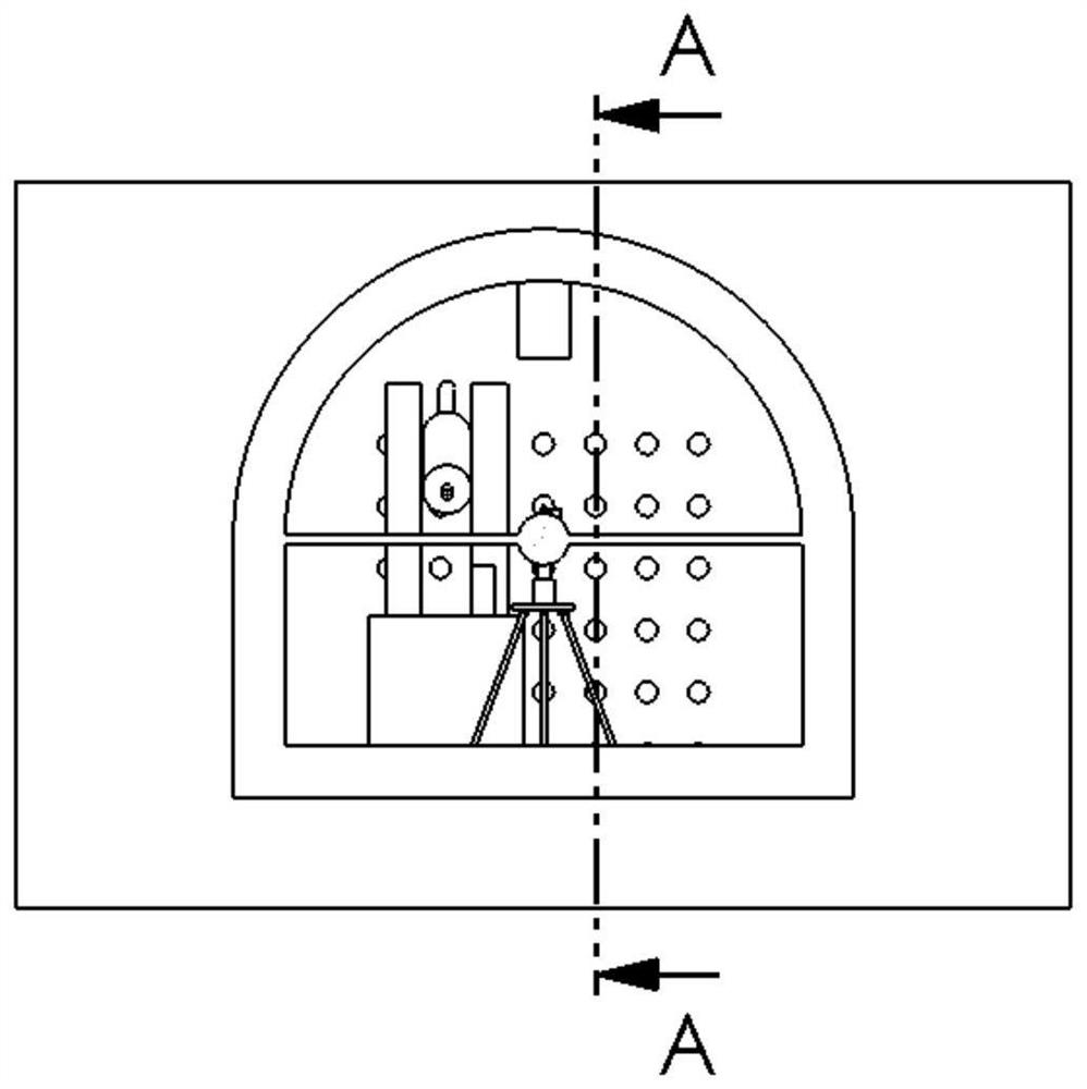
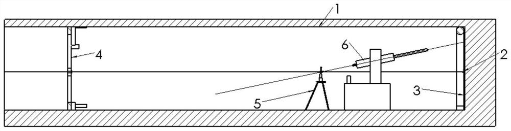
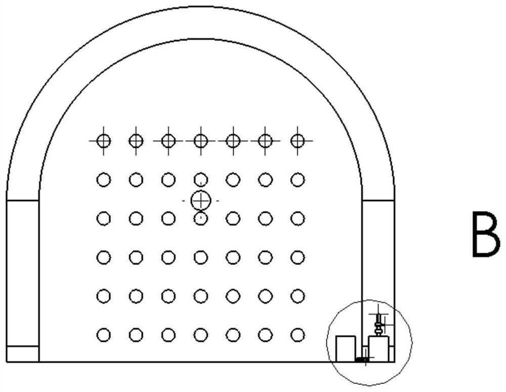
[0101] Implementation Example 1: Reference Figure 1 to Figure 16 , the present embodiment is a device for quickly specifying the azimuth angle of drilling, the device includes: an orifice positioning device 3, the orifice positioning device 3 is detachably installed on the working surface, and the orifice positioning device 3 is provided with A rectangular array 303 of circular holes with 6 rows and 7 columns; a centerline positioning device 304, the centerline positioning device 304 includes a fixed plate 201 and a first laser 202, the first laser 202 is arranged on the fixed plate 201, and the first laser 202 The central axis is perpendicular to the front surface of the fixed plate 201; the intersection positioning device 5, the intersection positioning device 5 includes a distance meter 507, a first frame body and an intersection positioning hole 506, and the intersection positioning hole 506 is arranged on the first frame body, measuring The tachymeter 507 is arranged on ...


PUM


Abstract

The invention discloses a device for quickly giving a azimuth angle of a drill hole. The device comprises a hole positioning apparatus which is detachably installed on a working face, a center line positioning apparatus which comprises a fixing plate and a first laser arranged on the fixing plate, an intersection point positioning apparatus which comprises a range finder arranged on a first framebody, the first frame body and an intersection point positioning hole formed in the first frame body, and a drill rod guiding apparatus which comprises a second laser and a universal mechanism, wherein the second laser is movably connected to the first frame body through the universal mechanism, and the central axis of the second laser passes through the center of the intersection point positioning hole. The problems that in the prior art, due to easy influence of the magnetism of ironware on the driving working face, the horizontal included angle between the drill hole and a center line is given inaccurately, and the azimuth angle of the drill hole is finally given inaccurately are solved.

Description

technical field [0001] The invention relates to the technical field of drilling, in particular to a device and method for rapidly setting the azimuth angle of drilling. Background technique [0002] When constructing gas drainage drilling in Shimen (well lane) coal excavation and excavation working face or in the drilling field, it is very important to set the azimuth angle of the drilling hole, and the correct setting of the azimuth angle of the turning hole is the key to measure the control range of the drilling hole an important factor. In the prior art, the compass is usually used to directly set the horizontal angle between the borehole and the center line, and then the vertical angle between the borehole and the center line is given by the gradient gauge. After the horizontal angle and the vertical angle are given, the The azimuth of the borehole is obtained. [0003] However, in the process of using the existing technology, it is found that because the excavation fa...

Claims


Application Information

Patent Timeline
IPC IPC(8): E21B15/04G01C1/00G01C15/00
CPCE21B15/04G01C1/00G01C15/004
Inventor 王吉斌赵建明罗文兵田俊康勇
Owner PANJIANG COAL & ELECTRICITY GROUP INSITUTE OF COAL MINING DESIGN
Why Eureka
Try Eureka