Capacitive vibration sensor and power plant fan diagnosis system and method

A vibration sensor and capacitive technology, applied in the direction of engines, wind turbines, machines/engines, etc., can solve the problems of reduced fan performance, hazards to human health and working environment, damage to blades and air ducts, etc., to achieve strong computing power, monitoring The effect of good effect and great application prospect

Pending Publication Date: 2021-01-29
大唐宝鸡第二发电有限责任公司
View PDF13 Cites 0 Cited by
  • Summary
  • Abstract
  • Description
  • Claims
  • Application Information

AI Technical Summary

Problems solved by technology

[0003] The fan will generate vibration signals during normal operation, but if the vibration of the fan exceeds the standard, it will cause damage to the bearing seat or motor bearing, loosening of the motor anchor bolts, damage to the fan casing, blades and air duct, and motor burning and heating. , which reduces the working performance of the fan and affects the normal work
Seriously, it may cause accidents due to vibration, endangering personal health and working environment

Method used


Image

  • Capacitive vibration sensor and power plant fan diagnosis system and method
  • Capacitive vibration sensor and power plant fan diagnosis system and method
  • Capacitive vibration sensor and power plant fan diagnosis system and method

Examples


Embodiment Construction

[0053] The present invention will be described in detail below in conjunction with the accompanying drawings and specific embodiments.

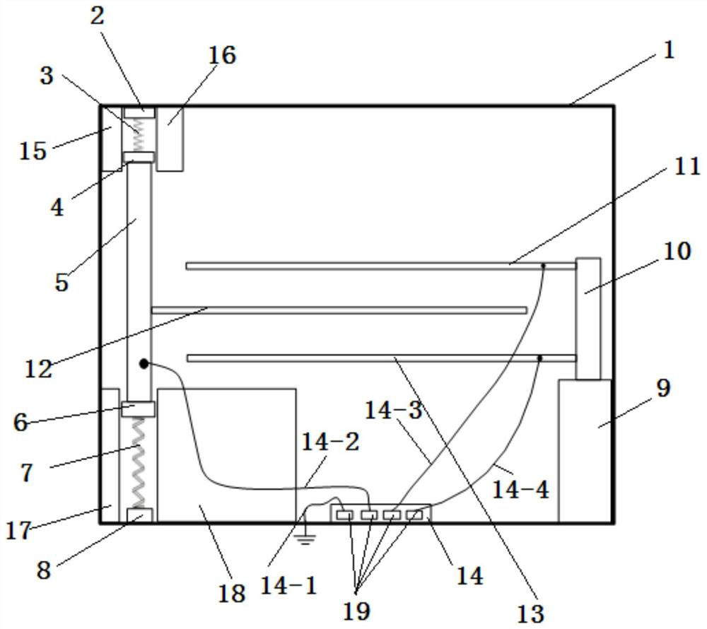
[0054] A kind of capacitive vibration sensor of the present invention, as figure 1 As shown, a housing 1 is included, and a first insulating gasket 2, an upper spring 3, a second insulating gasket 4, and a first conductive rod 5 are sequentially connected between the top plate and the bottom plate of the housing 1 from top to bottom. , the third insulating spacer 6, the lower spring 7 and the fourth insulating spacer 8, the bottom plate in the housing 1 is also provided with a resin pillar 9, the top of the resin pillar 9 is provided with a second conductive rod 10, the first conductive rod 5 Parallel to the second conductive rod 10, there are three capacitor plates parallel to each other between the first conductive rod 5 and the second conductive rod 10, which are: capacitor plate A11, capacitor plate B12 from top to bottom and the capacit...


PUM


Abstract

The invention discloses a capacitive vibration sensor which comprises a shell body, wherein a first insulating spacer, an upper spring, a second insulating spacer, a first conductive rod, a third insulating spacer, a lower spring and a fourth insulating spacer which are sequentially connected are arranged between a top plate and a bottom plate in the shell bodyfrom top to bottom, a resin supporting column is further arranged on the bottom plate in the shell body, the top part of the resin pillar is provided with the second conductive rod, the first conductive rod and the second conductive rodare parallel to each other, three capacitor plates which are parallel to each other are arranged between the first conductive rod and the second conductive rod, the bottom plate of the shell is further provided with a lead terminal unit, four lead wires are led out from the lead terminal unit, specifically, the firstlead wire is grounded, the second lead wire is connected with the first conductiverod, the third lead wire is connected with one end of the capacitor plate A, and the fourth wire is connected with one end of the capacitor plate C. The capacitive vibration sensor can realize acquisition of fan vibration signal data. The invention further discloses a power plant fan diagnosis system and method.

Description

technical field [0001] The invention belongs to the technical field of state monitoring of electric power equipment, and in particular relates to a capacitive vibration sensor, and also relates to a power plant blower diagnosis system and a power plant fan diagnosis method based on the capacitive vibration sensor. Background technique [0002] In recent years, the operation scale of my country's power system has been continuously expanding, and it has become very important to ensure the normal operation of various electrical equipment in the power system. With the continuous upgrading of the industry, the requirements for fans are getting higher and higher, especially for the efficiency, safety and performance of fans, which makes the fan equipment more automatic, more complex in structure, and more functional. More variety. [0003] The fan will generate vibration signals during normal operation, but if the vibration of the fan exceeds the standard, it will cause damage to...

Claims


Application Information

Patent Timeline
Patent Type & Authority Applications(China)
IPC IPC(8): G01H11/06F03D17/00
CPCG01H11/06F03D17/00
Inventor 孙海峰解鹏杨晟陈小强徐山吕建平
Owner 大唐宝鸡第二发电有限责任公司
Why Eureka
Try Eureka