Current sharing method for digital power supply parallel connection

A technology of digital power supply and parallel connection, which is applied in the direction of parallel operation of DC power supply, electrical components, circuit devices, etc., which can solve the problems of system paralysis, difficult adjustment, high cost, etc., and achieve the effect of good system stability and high current sharing accuracy

Pending Publication Date: 2021-01-29
广东高斯宝电气技术有限公司
View PDF0 Cites 3 Cited by
  • Summary
  • Abstract
  • Description
  • Claims
  • Application Information

AI Technical Summary

Problems solved by technology

Among them, the traditional analog current sharing technology needs to build an additional current sharing circuit, which has defects such as high cost, difficult maintenance, and difficult adjustment. However, the digital current sharing technology has become more popular with the intelligent processor technology with single-chip microcomputer, ARM and DSP as the core. Continuous innovation and development in the field of current sharing has been rapidly popularized. With its own advantages of high current sharing accuracy, easy implementation, and low cost, it has become a new direction for the development of power supply current sharing technology.
At present, the existing digital current sharing methods mainly include the output impedance method (also known as the external characteristic droop method or the slope method), the master-slave module setting method, etc., among which the current sharing accuracy of the output impedance method is low and depends on the hardware environment. It is used in occasions where the accuracy of current sharing is low; the master-slave setting method requires the system to participate in setting the master-slave module, the master module issues real-time adjustment instructions, and the slave module reports its own load information in real time. If the master module has a problem during the work, Then the whole system will be paralyzed

Method used


Image

  • Current sharing method for digital power supply parallel connection
  • Current sharing method for digital power supply parallel connection
  • Current sharing method for digital power supply parallel connection

Examples


Embodiment Construction

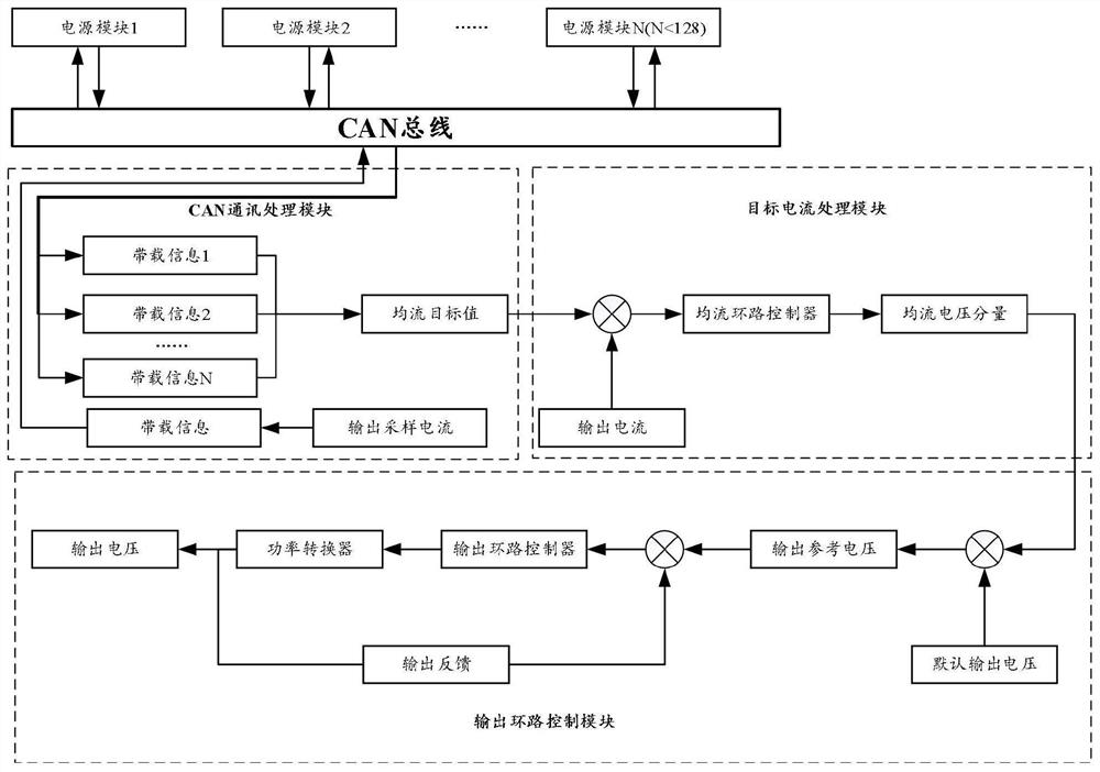
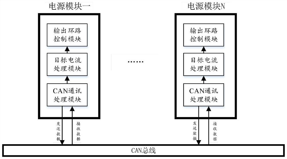
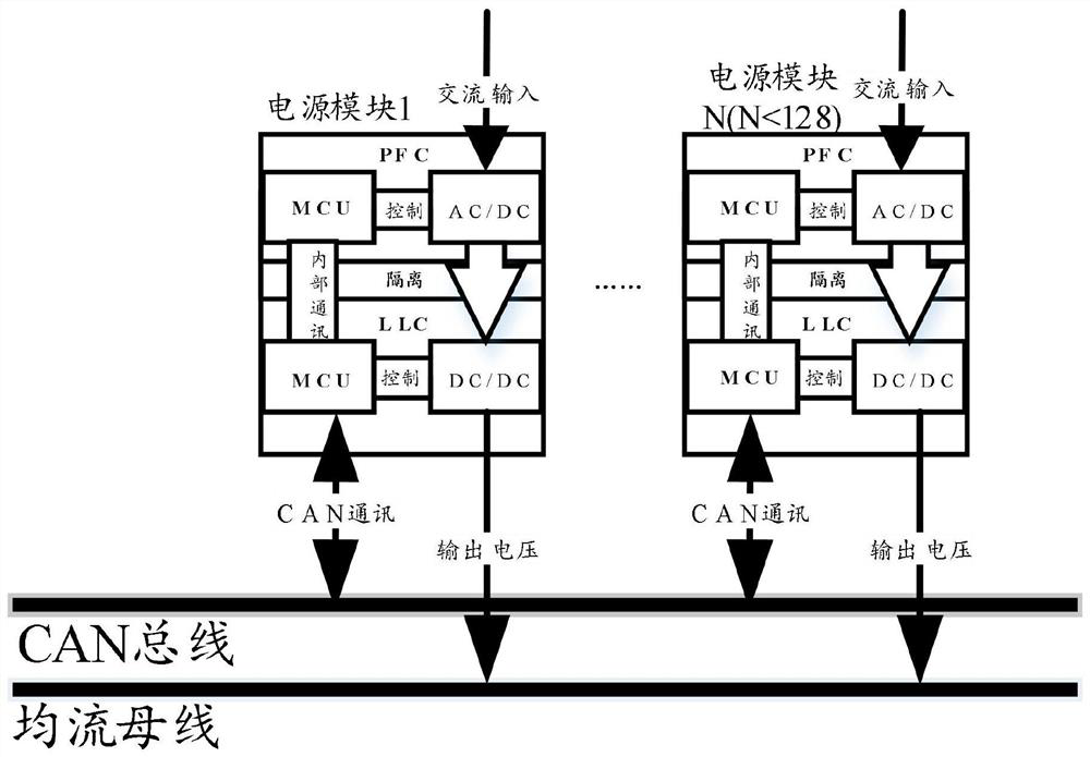
[0025] Such as figure 1 and figure 2 shown. The power supply module includes an output loop control module, a target current processing module and a CAN communication processing module.

[0026] All power modules in the whole system are connected together through the CAN bus, and each power module sends its own loading information to the CAN bus through its own CAN communication processing module, and at the same time retrieves the loading information of other power supplies on the CAN bus and saves it to the current sharing In the queue, and by processing the loading information in the flow-sharing queue, the current-sharing target value is obtained.

[0027] The function of the target current processing module is to make a difference between the self-sampled current and the current-sharing target value, and then pass through the current-sharing loop compensator to obtain the current-sharing voltage adjustment component.

[0028] The output loop control module will add th...


PUM


Abstract

The invention discloses a current sharing method for digital power supply parallel connection. A CAN communication processing module transmits load information of the CAN communication processing module to a CAN bus, the load information of other power supplies on the CAN bus is fished, and is preserved in a current sharing queue, and a current sharing target value is obtained through processing the load information in the current sharing queue; the target current processing module subtracts the sampling current of the target current processing module from the current-sharing target value andobtains a current-sharing voltage adjusting component through a current-sharing loop compensator; and an output loop control module adds the current-sharing voltage adjusting component and a default output voltage to obtain an output reference voltage, the difference between the output reference voltage and an output voltage sampling value is sent to an output loop compensator to calculate a driving value to adjust the output voltage, and the final current-sharing effect is achieved. The current sharing method is high in current sharing precision and good in system stability.

Description

[technical field] [0001] The invention relates to a digital power supply, in particular to a current sharing method for parallel connection of digital power supplies. [Background technique] [0002] With the rapid development of the national economy, high-power, high-stability DC power supplies have been widely used in fields such as industry, agriculture, and national defense. However, the cost of a single high-power switching power supply is high due to the influence of the semiconductor switching device's withstand voltage, operating frequency, and transformer magnetic materials and heat dissipation. increase, the reliability and stability of the power supply are greatly reduced. Therefore, it has become a general consensus to use multiple power modules in parallel to obtain higher power. [0003] When multiple power modules are used in parallel, each power module cannot be simply connected in parallel to share the load power. This is because the electrical characterist...

Claims


Application Information

Patent Timeline
Patent Type & Authority Applications(China)
IPC IPC(8): H02J1/10H02J13/00
CPCH02J1/102H02J13/00016
Inventor 赵锦阮世良慕德世龙东东
Owner 广东高斯宝电气技术有限公司
Why Eureka
Try Eureka