Ultra-wide gain range adjusting method of L-LLC resonant converter

A technology of resonant converter and adjustment method, which is applied in the direction of adjusting electrical variables, control/regulation systems, and converting DC power input to DC power output, etc., which can solve the problem that the range of L-LLC topology gain is limited and the output voltage range cannot meet the requirements And other issues

Active Publication Date: 2021-01-29
BEIJING JIAOTONG UNIV +1
View PDF8 Cites 2 Cited by
  • Summary
  • Abstract
  • Description
  • Claims
  • Application Information

AI Technical Summary

Problems solved by technology

[0005] Aiming at the problem that the gain range of the L-LLC topology is limited and the output voltage range cannot meet the requirements, the present invention proposes a method for adjusting the ultra-wide gain range of the L-LLC resonant converter, w

Method used


Image

  • Ultra-wide gain range adjusting method of L-LLC resonant converter
  • Ultra-wide gain range adjusting method of L-LLC resonant converter
  • Ultra-wide gain range adjusting method of L-LLC resonant converter

Examples


Embodiment Construction

[0054] The present invention will be described in further detail below in conjunction with the accompanying drawings.

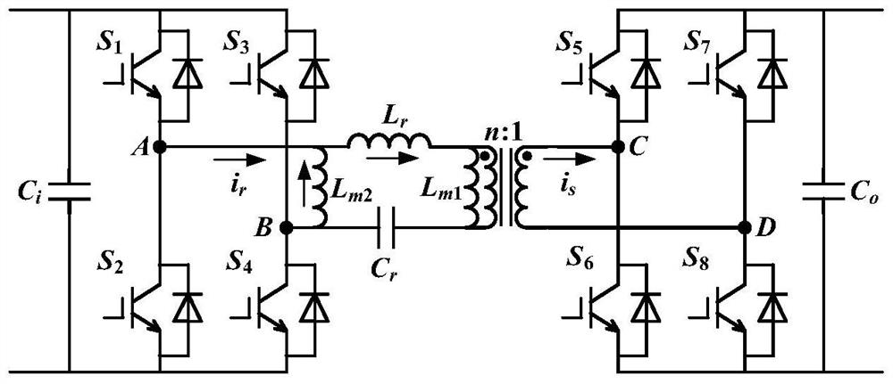
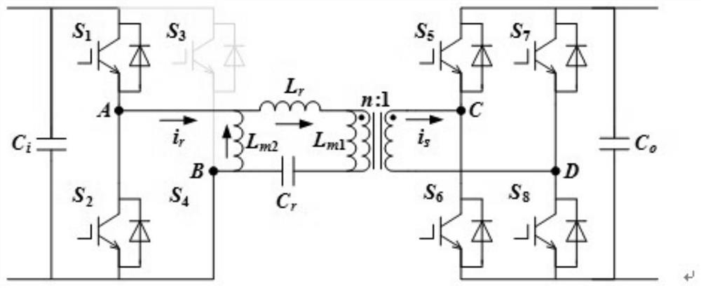
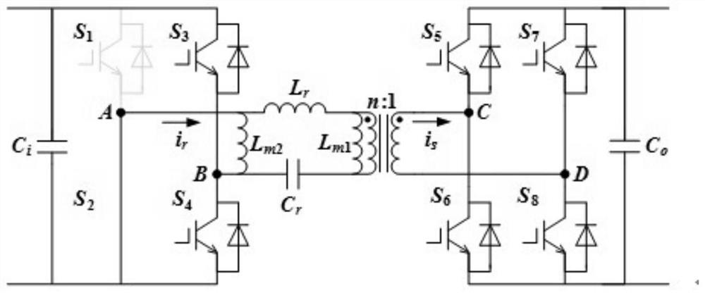
[0055] The present invention provides an ultra-wide gain range adjustment method for an L-LLC resonant converter, which is applied to an L-LLC bidirectionally isolated DC power electronic transformer with auxiliary inductance. The following is combined with the attached Figure 1-5 , the DC power electronic transformer topology that can perform full-bridge topology to half-bridge topology for L-LLC provided by the present invention is described in detail. figure 1 is a schematic structural diagram of an L-LLC full-bridge topology in an embodiment of the present invention, figure 2 and image 3 It is two structural schematic diagrams of L-LLC full-bridge topology switching to half-bridge topology in the embodiment of the present invention. The L-LLC resonant converter is composed of a primary side H bridge, a medium and high frequency transformer, a secondar...


PUM


Abstract

The invention provides an ultra-wide gain range adjusting method of an L-LLC resonant converter, and is suitable for the fields of flexible direct current transmission, power distribution networks, new energy grid connection, storage battery energy storage and the like which use the wide voltage range L-LLC resonant converter. According to the method for adjusting the ultra-wide gain range of theL-LLC resonant converter, the wide-range voltage adjusting capacity is given to the L-LLC resonant converter, the good soft switching characteristic of the L-LLC resonant converter is guaranteed, andthe bridge arm control is optimized and the magnetic bias phenomenon introduced by the auxiliary inductor is eliminated according to the ultra-wide gain range adjusting method.

Description

technical field [0001] The invention relates to an ultra-wide gain range adjustment method of an L-LLC resonant converter, which is suitable for all medium and high voltage bidirectional isolated DC power electronics that may be used in flexible DC transmission and distribution networks, new energy grid connection, battery energy storage, etc. field of transformers. Background technique [0002] Power Electronic Transformer (PET), also known as Solid State Transformer (SST), is an electronic power device that replaces traditional transformers through high-frequency energy conversion technology. The power electronic transformer used for energy transmission and electrical isolation between two DC buses is also called DC Power Electronic Transformer (DCPET). DCPET is widely used in flexible DC transmission and distribution networks, new energy grid connection, energy Internet and other fields where medium and high voltage bidirectional isolated DC conversion may be used. The ...

Claims


Application Information

Patent Timeline
IPC IPC(8): H02M3/335
CPCH02M3/33584Y02B70/10
Inventor 刘建强艾宇张泽辉陈少勇赵帅史芸铭袁宇波史明明刘瑞煌姜云龙肖小龙孙天奎
Owner BEIJING JIAOTONG UNIV
Why Eureka
Try Eureka