Automatic succulent plant juice extraction equipment
A technology of succulent plants and equipment, which is applied in the field of equipment for automatic sap extraction of succulent plants, and can solve problems such as slow speed
- Summary
- Abstract
- Description
- Claims
- Application Information
AI Technical Summary
Problems solved by technology
Method used
Image

Examples
Embodiment 1
[0023] A kind of equipment for automatic succulent plant juice extraction, such as figure 1 As shown, it includes a base plate 1, a servo motor 2, a first storage basket 3, a transmission mechanism 4, and a pressing mechanism 5. The servo motor 2 is provided on the right rear side of the upper part of the base plate 1, and the first storage basket is provided on the left side of the upper part of the base plate 1. 3. The upper part of the bottom plate 1 is provided with a transmission mechanism 4, and the upper part of the bottom plate 1 is provided with a pressing mechanism 5.
[0024] When the user needs to squeeze the juice of the succulent plants, the device can be used. First, the succulent plants to be squeezed are placed in the pressing mechanism 5, and then the servo motor 2 is turned on, and the transmission mechanism 4 is driven by the servo motor 2 The components are operated, and the conveying mechanism 4 drives the pressing mechanism 5 to squeeze the pulpy plants....
Embodiment 2
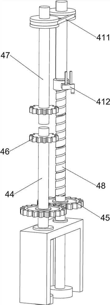
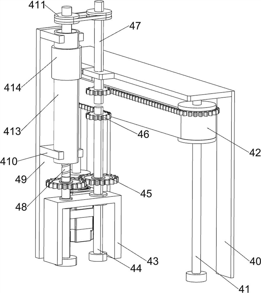
[0026] On the basis of Example 1, such as Figure 2-5 As shown, the transmission mechanism 4 includes a first supporting frame 40, a first rotating shaft 41, a toothed pulley assembly 42, a second supporting frame 43, a second rotating shaft 44, a first gear 45, a second gear 46, and a third rotating shaft 47 , screw mandrel 48, the third support frame 49, fixed plate 410, the first pulley assembly 411, slide block 412, guide pipe 413 and the first round pipe 414, the bottom plate 1 upper right side is provided with the first support frame 40, bottom plate 1 A first rotating shaft 41 is rotatably provided between the upper right front side and the first support frame 40, and a toothed pulley assembly 42 is connected between the first rotating shaft 41 and the output shaft of the servo motor 2. Support frame 43, the second support frame 43 is rotatably provided with a second rotating shaft 44, the second rotating shaft 44 is rotatably connected with the base plate 1, and the fi...
Embodiment 3
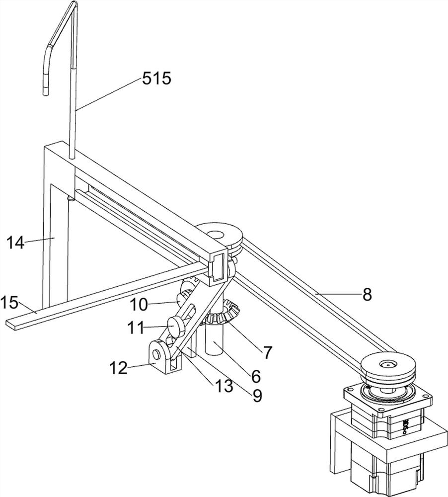
[0031] On the basis of Example 2, such as Image 6 As shown, it also includes a fourth rotating shaft 6, a bevel gear 7, a second pulley assembly 8, a second support plate 9, a rotating plate 10, a connecting rod 11, a fixed block 12, a guide plate 13 and a scraper 14, and the upper part of the bottom plate 1 The middle of the rear side is rotated with a fourth rotating shaft 6, a second pulley assembly 8 is connected between the fourth rotating shaft 6 and the servo motor 2, and a second support plate 9 is arranged in the middle of the upper rear side of the bottom plate 1, on which the second support plate 9 rotates. The formula is provided with a rotating rod, and the rotating rod and the fourth rotating shaft 6 are provided with bevel gears 7, and the two bevel gears 7 are meshed. The block 12 is rotatably provided with a guide plate 13, the guide plate 13 is slidably provided with a connecting rod 11, the connecting rod 11 is rotatably connected with the rotating plate 10...
PUM
 Abstract
Description
Claims
Application Information
 - R&D
- Intellectual Property
- Life Sciences
- Materials
- Tech Scout
- Unparalleled Data Quality
- Higher Quality Content
- 60% Fewer Hallucinations
Browse by: Latest US Patents, China's latest patents, Technical Efficacy Thesaurus, Application Domain, Technology Topic, Popular Technical Reports.
© 2025 PatSnap. All rights reserved.Legal|Privacy policy|Modern Slavery Act Transparency Statement|Sitemap|About US| Contact US: help@patsnap.com