Disassembly method of bending tool and rotor retaining ring

A tool and workpiece technology, applied in the field of engine assembly, can solve the problems of non-unique installation positions of special baffles 32, large bending angles, damage to blades 2, etc.

Active Publication Date: 2021-04-02
AECC SHANGHAI COMML AIRCRAFT ENGINE MFG CO LTD +1
View PDF9 Cites 0 Cited by
  • Summary
  • Abstract
  • Description
  • Claims
  • Application Information

AI Technical Summary

Problems solved by technology

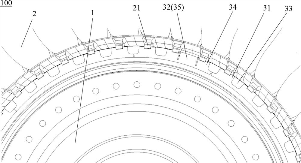
[0005] When decomposing the retaining ring 3, it is necessary to bend the bendable retainer 35 to form the avoidance groove 33. Since the bendable retainer 35 is an eversion structure, the conventional disassembly process is to use a screwdriver to pry the bendable retainer 35 and the blade In the gap of 2, the edge plate of the blade needs to be used as the fulcrum of the screwdriver when prying. Since the edge plate of the blade is thin, it cannot withstand excessive pressure. Using this method will easily cause damage to the blade 2.
In addition, the bendable baffle 35 can be stuck between the tenons 21 of any two adjacent blades 2 in the unbent state, that is, the installation position of the special baffle 32 is not unique, and when disassembled, the bendable baffle 35 needs to be bent at nearly 90°, and the bending angle is relatively large. Conventional bending tools are difficult to meet the requirements

Method used


Image

  • Disassembly method of bending tool and rotor retaining ring
  • Disassembly method of bending tool and rotor retaining ring
  • Disassembly method of bending tool and rotor retaining ring

Examples


Embodiment Construction

[0039] A variety of different implementations or examples for implementing the described subject technical solutions are disclosed below. In order to simplify the disclosure, the following describes the specific examples of each component and arrangement, of course, these are only examples, not limiting the protection scope of the present invention. For example, the description that the first feature described later in the description is formed on or above the second feature may include an embodiment in which the first and second features are formed through direct contact, and may also include an embodiment in which the first and second features are formed between the first and second features. Embodiments of additional features such that there may be no direct relationship between the first and second features. Additionally, reference numerals and / or letters may be repeated in different instances in these disclosures. This repetition is for brevity and clarity and does not i...


PUM


Abstract

The invention provides a method for disassembling a bending tool and a rotor retaining ring, which can apply a pulling force consistent with the deformation direction of a bent workpiece. In the bending tool: the sliding seat is slidingly fitted with the support; the hook seat is rotatably connected with the sliding seat; the hook includes a rod that is slidingly fitted with the hook seat and a hook for hooking the workpiece to be bent; the length of the rod The direction is perpendicular to the bending rotation center line of the workpiece to be bent, the sliding direction of the rod relative to the hook seat is along the length direction of the rod, the sliding direction of the sliding seat relative to the support intersects the length direction of the rod and is in line with the bending direction. The center line of rotation is vertical, and the axis of rotation of the draw hook seat relative to the sliding seat is parallel to the center line of bending rotation. The decomposition method of the rotor retaining ring adopts the bending tool, including: hooking the hook to the bendable block; operating the hook to pull the bendable block to bend, adjusting the position of the slide seat relative to the support during the bending process, The position of the rod relative to the hook seat and the angle of the hook make the hook perpendicular to the bendable blocking piece.

Description

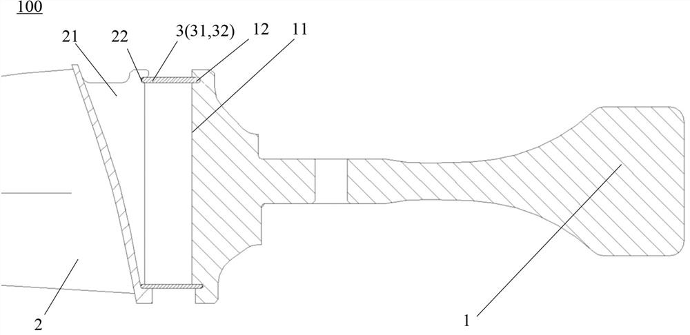
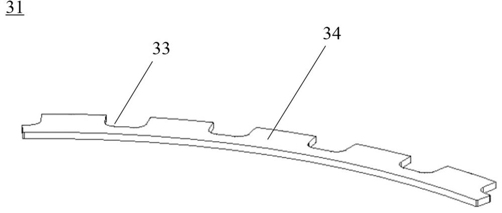
technical field [0001] The invention relates to the technical field of engine assembly, in particular to a bending tool and a method for disassembling a rotor retaining ring. Background technique [0002] A new type of engine compressor rotor 100 such as figure 1 and 2 As shown, it includes a rotor disk 1, a plurality of blades 2 and a multi-segment retaining ring 3, and the plurality of blades 2 are respectively connected with a plurality of grooves 11 in the circumferential direction of the rotor disk 1 through a dovetail or fir tree tenon 21, so as to limit the 2 degrees of freedom of movement in the circumferential direction, the multi-segment retaining ring 3 is installed in the drum slot 12 of the rotor disk 1 and the tenon slot 22 of the blade 2 to limit the freedom of movement of the blade 2 in the axial direction. [0003] Multi-stage retaining ring 3 such as Figure 1 to Figure 5 As shown, it includes a plurality of normal baffles 31 and at least one special baf...

Claims


Application Information

Patent Timeline
Patent Type & Authority Patents(China)
IPC IPC(8): B23P19/00B21D11/10B21D53/84
CPCB21D11/10B21D53/84B23P19/00
Inventor 欧阳醌周晓丽周宇乾
Owner AECC SHANGHAI COMML AIRCRAFT ENGINE MFG CO LTD
Why Eureka
Try Eureka