Injection mold

An injection mold and injection molding machine technology, applied in the field of molds, can solve the problems of blockage of vent holes, affecting the normal use of molds, and difficult to control the balance, so as to improve the buffer effect and increase the difficulty of using the mold.

Inactive Publication Date: 2021-02-02
陈盈
View PDF1 Cites 4 Cited by
  • Summary
  • Abstract
  • Description
  • Claims
  • Application Information

AI Technical Summary

Problems solved by technology

When the existing mold is installed and used for the first time, there may be a slight misalignment between the movable mold and the fixed mold in the mold. When the two molds are closed, it is easy to cause bumps between the movable mold and the fixed mold, resulting in damage to the parting surface of the mold. It affects the normal use of the mold. At the same time, during the use of the mold, the balance between the air discharge in the mold and the sealing performance of the mold is difficult to control. When the sealing performance of the mold is improved, it is easy to cause inconvenience in the air discharge in the mold and affect the product. When reducing the difficulty of air discharge in the mold, it is easy to cause poor sealing of the mold, resulting in the plastic liquid overflowing into the gap between the molds during injection molding, resulting in flashing of the product. At the same time, during use, between the molds The mutual locking depends on the external clamping force. There is no mutual locking between the molds, and insufficient clamping force is prone to occur, which will cause the molds to separate from each other during the injection molding process, and gaps will appear, causing flashes on the product and affecting the quality of the product.
[0003] There are also some technical solutions in the prior art, such as the Chinese patent with the application number CN201921717818.X, which includes a fixed mold and a movable mold, the surfaces of the fixed mold and the movable mold are provided with mold cores, and the side surfaces of the fixed mold The limit rod is fixed, the side surface of the movable mold is provided with a limit groove, the surface of the limit rod is provided with a positioning groove, and the inner surface of the limit groove is equipped with a positioning protrusion matching the positioning groove The limit rod is inserted into the inside of the limit groove, and the surfaces of the fixed mold and the movable mold are provided with vent holes; the positioning groove provided on the surface of the limit rod and the positioning device installed on the inner surface of the limit groove When the limit rod is inserted into the inside of the limit groove, the positioning protrusion slides inside the positioning groove, so that when the limit rod is installed inside the limit groove, it is positioned through the positioning groove and the positioning protrusion, avoiding When the fixed mold and the movable mold are laminated in reverse, the collision caused by the misalignment of the mold core set on the surface of the fixed mold and the movable mold is avoided; Insufficient mold force leads to flashing of the product. At the same time, in the process of use, the mold in this solution discharges the air in the mold through the vent hole, which cannot completely prevent the plastic liquid in the mold from entering the vent hole or passing through the vent hole. Outflow, it is easy to cause the blockage of the vent hole and affect the operation of pressurizing the mold to improve product quality during the injection molding process

Method used


Image

  • Injection mold
  • Injection mold
  • Injection mold

Examples


Embodiment approach

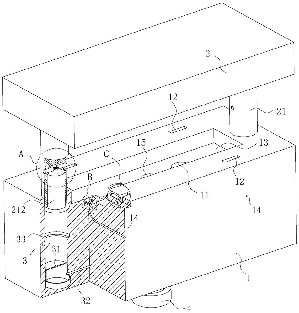
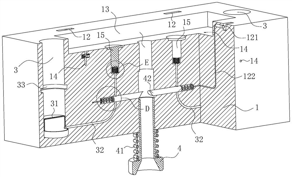
[0035] As an embodiment of the present invention, the fixed mold 1 is provided with a movable chamber 2 151; the center line of the movable chamber 151 is perpendicular to the bottom surface of the lower cavity 13 on the fixed mold 1; the movable chamber 2 Ejector rod 15 is installed in 151; The upper end of described ejector rod 15 is positioned in lower cavity 13, and the upper surface of the upper end of ejector rod 15 is flush with the bottom surface of lower cavity 13; Described ejector rod 15 can Move up and down in the second movable chamber 151; a tension spring one 152 is installed in the second movable chamber 151; ; The fixed mold 1 is provided with an air passage 32; the two ends of the air passage 32 communicate with the two movable chambers 151 and the air bag 31 respectively; the air passage 32 runs through the movable chamber three 423; The through hole 421; the air channel 32 is communicated in the movable chamber three 423 through the through hole 421; when t...


PUM


Abstract

The invention belongs to the technical field of molds, and particularly relates to an injection mold. The injection mold comprises a movable mold and a fixed mold, wherein an upper cavity is formed inthe movable mold; a positioning rod is installed on the movable mold; a lower cavity is formed in the fixed mold; a positioning hole is formed in the fixed mold; the positioning rod is inserted intothe positioning hole; a guide groove is formed in the positioning rod; a positioning protrusion is arranged on the inner wall of the positioning hole and can be inserted into the guide groove; an airbag is installed on the bottom face of the positioning hole; the bottom face of the positioning rod can make contact with the air bag and extrude the air bag; an injection molding hole is formed in the bottom face of the lower cavity in the fixed mold; a lining is installed in the injection molding hole; a first spring is installed on the lining; a third movable cavity is formed in the fixed mold;a buffer rod and a second spring are installed in the third movable cavity; and an air leakage hole is formed in the fixed mold. The injection mold is accurate in positioning, the mold is not prone to loosening after being assembled, and meanwhile air in the mold can be conveniently exhausted.

Description

technical field [0001] The invention belongs to the technical field of moulds, in particular to an injection mould. Background technique [0002] Mold, various molds and tools used in industrial production for injection molding, blow molding, extrusion, die-casting or forging forming, smelting, stamping and other methods to obtain the required products. A mold is a tool used to make shaped objects. This tool is composed of various parts, and different molds are composed of different parts. It mainly realizes the processing of the shape of the article through the change of the physical state of the formed material. When the existing mold is installed and used for the first time, there may be a slight misalignment between the movable mold and the fixed mold in the mold. When the two molds are closed, it is easy to cause bumps between the movable mold and the fixed mold, resulting in damage to the parting surface of the mold. It affects the normal use of the mold. At the same...

Claims


Application Information

Patent Timeline
Patent Type & Authority Applications(China)
IPC IPC(8): B29C45/26B29C45/34B29C45/66
CPCB29C45/26B29C45/2606B29C45/34B29C45/66
Inventor 陈盈欧良明
Owner 陈盈
Why Eureka
Try Eureka