Gait detection device based on plantar pressure

A technology of gait detection and plantar pressure, applied in the field of robotics, can solve the problems of large volume and weight of the gravity sensor, large resistance value deviation, sensor failure, etc., to avoid foot health problems, reduce requirements, and simplify the wearing process Effect

Pending Publication Date: 2021-02-02
THE 21TH RES INST OF CHINA ELECTRONIC TECH GRP CORP
View PDF0 Cites 1 Cited by
  • Summary
  • Abstract
  • Description
  • Claims
  • Application Information

AI Technical Summary

Problems solved by technology

The weighing force sensor based on the resistance strain gauge has better accuracy, but the volume and weight of the weighing force sensor with a suitable range are relatively large, and it is rigid, so it is not suitable for placement on the sole of the foot; the thin film pressure sensor based on the piezoresistive effect Small in size and weight, it can be pasted under the insole and is convenient for application. However, since the thin film pressure sensor is based on the preparation process of the flexible circuit board, it can only be bent with a certain radius of curvature in the one-dimensional direction and has no elasticity. After sticking to the inside of the shoe, since the sticking position is not on the neutral layer of the sole, the sole will bend with the movement of the human body, and the film-type pressure sensor pasted in the direction of the insole will bear periodic compressive stress, which will easily cause the internal wire to break and cause the entire The sensor fails, the service life is short, and the initial resistance value of each sheet of the thin-film pressure sensor and the resistance change value after pressure are also inconsistent, and the soles of th

Method used


Image

  • Gait detection device based on plantar pressure
  • Gait detection device based on plantar pressure
  • Gait detection device based on plantar pressure

Examples


Embodiment Construction

[0032] The present application will be described in detail below with reference to the accompanying drawings and embodiments. Each example is provided by way of explanation of the application, not limitation of the application. In fact, those skilled in the art will recognize that modifications and variations can be made in the present application without departing from the scope or spirit of the application. For example, features illustrated or described as part of one embodiment can be used on another embodiment to yield a still further embodiment. Accordingly, it is intended that the present application cover such modifications and variations as come within the scope of the appended claims and their equivalents.

[0033] In the description of this application, the terms "vertical", "transverse", "upper", "lower", "front", "rear", "left", "right", "vertical", "horizontal", " The orientation or positional relationship indicated by "top", "bottom", etc. is based on the orien...


PUM


Abstract

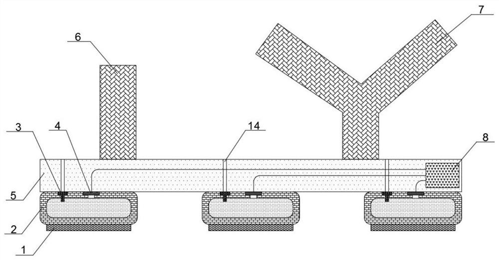
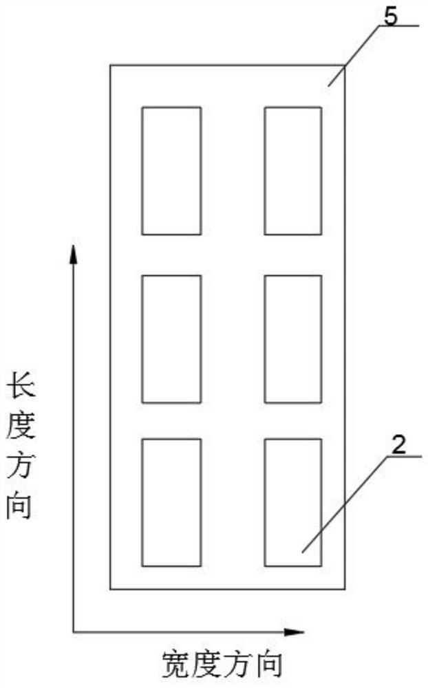
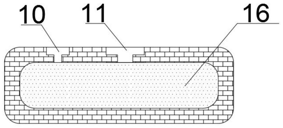
The invention provides a gait detection device based on plantar pressure. The gait detection device comprises a sole plate, a sole air bag and a signal processing unit, wherein a magic tape is arranged on the foot bottom plate and is used for fixing the foot of the target object on the foot bottom plate; a plurality of plantar air bags are arranged, and the plurality of plantar air bags are not communicated with one another and are arranged on the bottom surface of the plantar plate in a matrix manner; an air pressure detection hole is formed in each plantar air bag, and an air pressure sensoris arranged at each air pressure detection hole so as to detect the air pressure in the corresponding plantar air bag when the plantar air bag is pressed to deform in the walking process of the target object; a signal processing unit is located on the sole plate, electrically connected with the air pressure sensor and used for processing a pressure signal, detected by the air pressure sensor, ofthe sole air bag. The deformation of the plantar air bag of the device does not drive the stress deformation of the air pressure sensor and is not influenced by the ectropion or ectropion of the anklejoint of the target object, the requirement on the detection condition is reduced, and the service life is prolonged.

Description

technical field [0001] The present application relates to the field of robot technology, in particular to a gait detection device based on plantar pressure. Background technique [0002] Wearable exoskeleton robots can provide functions such as power assistance, protection, and body support for people's lower limbs. It integrates robotic technologies such as sensing, control, information acquisition, and mobile computing. A human-machine integrated system that assists functions and tasks such as walking. However, the current lower extremity exoskeleton robots still face many problems. For example, in the process of walking, different gait phases will cause different torques applied to each assist joint. Equal phases are implemented to provide appropriate torque to each joint. If there is not enough gait phase transition, the distribution of torque by the system will change suddenly, resulting in shock and vibration, which seriously affects user experience and walking stabil...

Claims


Application Information

Patent Timeline
IPC IPC(8): G01L5/00A61B5/11A61B5/103A61B5/00
CPCA61B5/1038A61B5/112A61B5/6807G01L5/0038
Inventor 芮岳峰杨亚王春雷范春辉黄显道黄浩蔡沂恒马保平李昀佶
Owner THE 21TH RES INST OF CHINA ELECTRONIC TECH GRP CORP
Why Eureka
Try Eureka