Nondestructive testing equipment and nondestructive testing method

A non-destructive testing and equipment technology, applied in the direction of using radiation for material analysis, etc., can solve the problems of increasing the labor intensity of boarding operators, and achieve the effects of improving equipment use efficiency, optimizing operation process, and improving safety and reliability

Pending Publication Date: 2021-02-02
CHINA ELECTRIC POWER RES INST +2
View PDF0 Cites 7 Cited by
  • Summary
  • Abstract
  • Description
  • Claims
  • Application Information

AI Technical Summary

Problems solved by technology

However, when the existing non-destructive testing devices carry out the non-destructive testing of the crimping quality of the tension clamp, the crimping operation is usually completed at high altitude and the wire is hung up, and the non-destructive testing personnel carry the non-destructive testing device to carry out the high-altitude operation, and carry out the tension clamp at high altitude. Non-destructive testing of crimp quality
Since the non-destructive testing operation is carried out after the line is hung, there is a situation where the tension clamp crimps the sick hanging line, and it needs to be re-hanged after non-destructive testing and correction, which increases the labor intensity of the boarding operators.

Method used


Image

  • Nondestructive testing equipment and nondestructive testing method
  • Nondestructive testing equipment and nondestructive testing method
  • Nondestructive testing equipment and nondestructive testing method

Examples


Embodiment 1

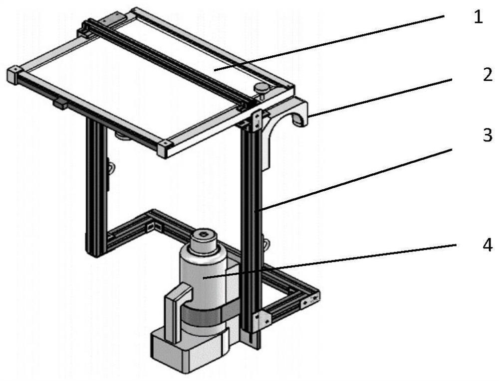
[0045] Existing complete sets of X-ray imaging technology devices such as figure 2 shown. The main components are an X-ray pulse machine A4, a digital flat panel detector A1, a U-shaped groove 2 and a bracket 3 to assemble a detection device.

[0046]In the existing non-destructive testing of the crimping quality of tension clamps, after the crimping operation is completed at high altitude and the wire is hung, the non-destructive testing personnel carry the non-destructive testing device to carry out the high-altitude operation, and carry out the non-destructive testing of the crimping quality of the strain clamps at high altitude. When carrying out non-destructive testing of the crimping quality of the tension clamp, it needs to be suspended on the tension clamp through the U-shaped groove 2 to ensure the relative position of the detection device and the tension clamp. Due to the long crimping length of the tension clamp, it is necessary to use the non-destructive testing ...

Embodiment 2

[0065] After the crimping operation of the strain clamp is completed, the crimping-related equipment in the aerial work platform for the dismantled crimping can be used for non-destructive testing of the strain clamp.

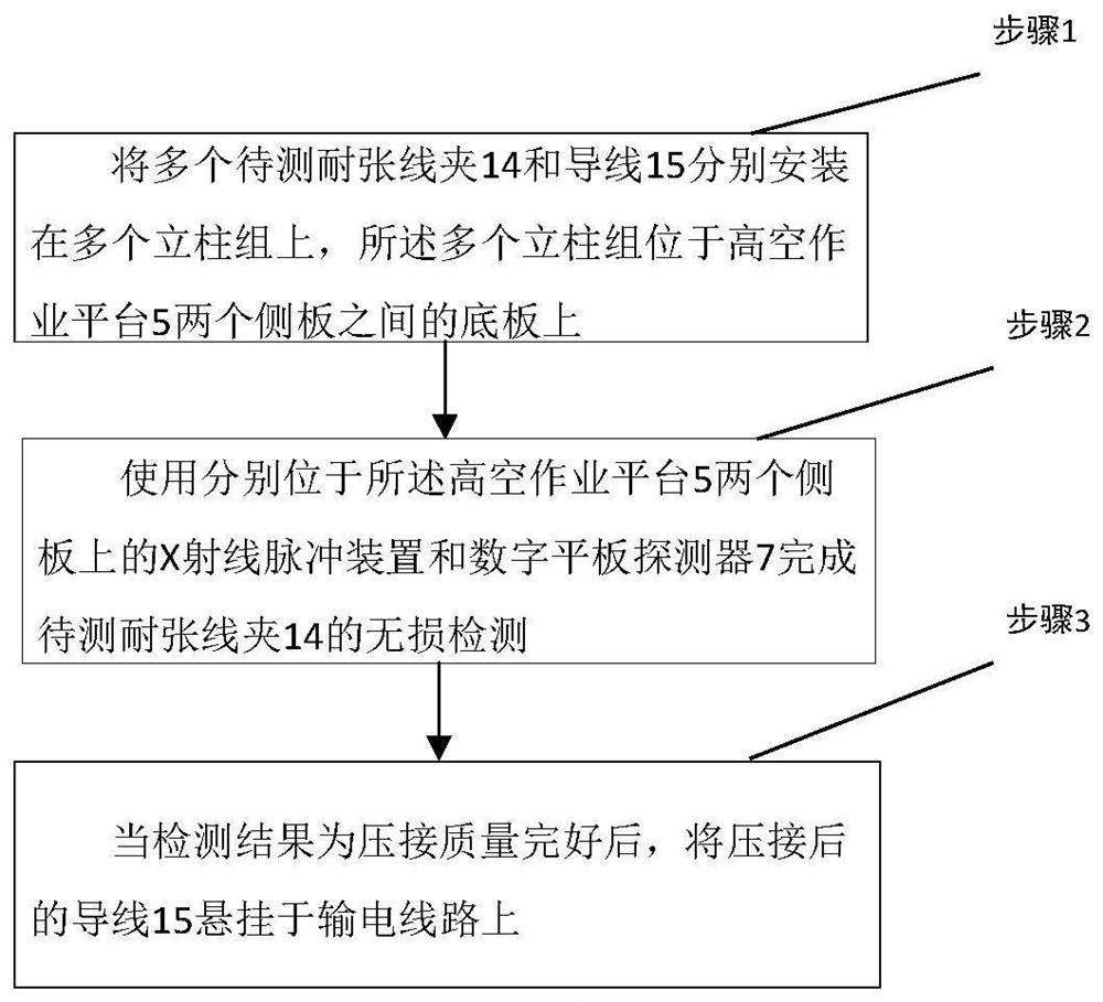
[0066] A non-destructive testing method such as image 3 shown, including:

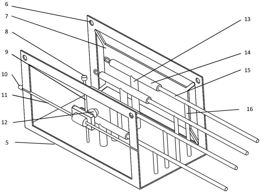
[0067] Step 1: install a plurality of tension clamps 14 and wires 15 to be tested on a plurality of column groups respectively, and the plurality of column groups are located on the bottom plate between the two side plates of the aerial work platform 5;

[0068] Step 2: use the X-ray pulse device and the digital flat panel detector 7 respectively located on the two side plates of the aerial work platform 5 to complete the non-destructive testing of the tension clamp 14 to be tested;

[0069] Step 3: When the test result shows that the crimping quality is intact, hang the crimped wire 15 on the power transmission line.

[0070] Step 2: Using the X-ray pulse device and the digital flat...


PUM


Abstract

The invention discloses nondestructive testing equipment. The nondestructive testing equipment is mounted on an aerial work platform 5 for crimping; the equipment comprises an X-ray pulse device, a digital flat panel detector 7 and a plurality of upright post groups, the X-ray pulse device is mounted on one side plate of the aerial work platform 5 for crimping; the digital flat panel detector 7 ismounted on the other side plate of the aerial work platform 5 for crimping; the plurality of upright post groups are arranged on a bottom plate of the aerial work platform 5 for crimping, are positioned between the X-ray pulse device and the digital flat panel detector 7, and are respectively used for supporting a plurality of strain clamps 14 to be tested; and the aerial work platform 5 for crimping is used for crimping the strain clamp 14 and the wire 15. According to the technical scheme provided by the invention, the nondestructive testing equipment is mounted on the aerial work platformfor crimping, and the strain clamp is fixed by utilizing the plurality of upright post groups so that the use efficiency of the equipment is improved, and the operation process is optimized.

Description

technical field [0001] The invention relates to power transmission and transformation construction technology, in particular to a non-destructive testing device and a non-destructive testing method. Background technique [0002] During the wire tension stringing construction process, the wire connection needs to be crimped, including the crimping of the splicing tube and the crimping of the tension clamp. Splice tubes and strain clamps are important components of line fittings, and their crimping quality is related to the grip of the wires. The concealed crimping project of the strain clamp and the straight connecting pipe has a great relationship with the skill level of the construction personnel and whether the operation is standardized. In addition, because the strain clamp belongs to high-altitude operations, it is not easy to fully supervise the site, resulting in poor quality of wire crimping. The crimping of strain clamps and splicing tubes that do not meet the requi...

Claims


Application Information

Patent Timeline
Patent Type & Authority Applications(China)
IPC IPC(8): G01N23/18
CPCG01N23/18
Inventor 彭飞乔亚霞徐玲玲吴念朋郝玉靖刘晨周亚傲马勇乔汉文张浩
Owner CHINA ELECTRIC POWER RES INST
Why Eureka
Try Eureka