Radar beam forming system and transmitting and receiving method based on same

A receiving method and beam technology, which is applied in the field of optical beam forming systems, can solve the problems that two-dimensional area array beam scanning cannot be used

Pending Publication Date: 2021-02-02
CHINA ELECTRONICS TECH GRP CORP NO 14 RES INST
View PDF0 Cites 3 Cited by
  • Summary
  • Abstract
  • Description
  • Claims
  • Application Information

AI Technical Summary

Problems solved by technology

Since the optical path difference between each channel is equal and can only be changed in proportion, the pure dispersion delay method is only suitable for one-dimensional linear arrays, but not for beam scanning of two-dimensional arrays

Method used


Image

  • Radar beam forming system and transmitting and receiving method based on same
  • Radar beam forming system and transmitting and receiving method based on same
  • Radar beam forming system and transmitting and receiving method based on same

Examples


Embodiment 1

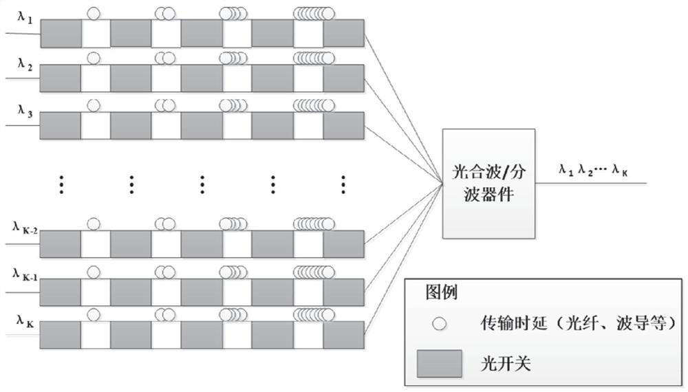
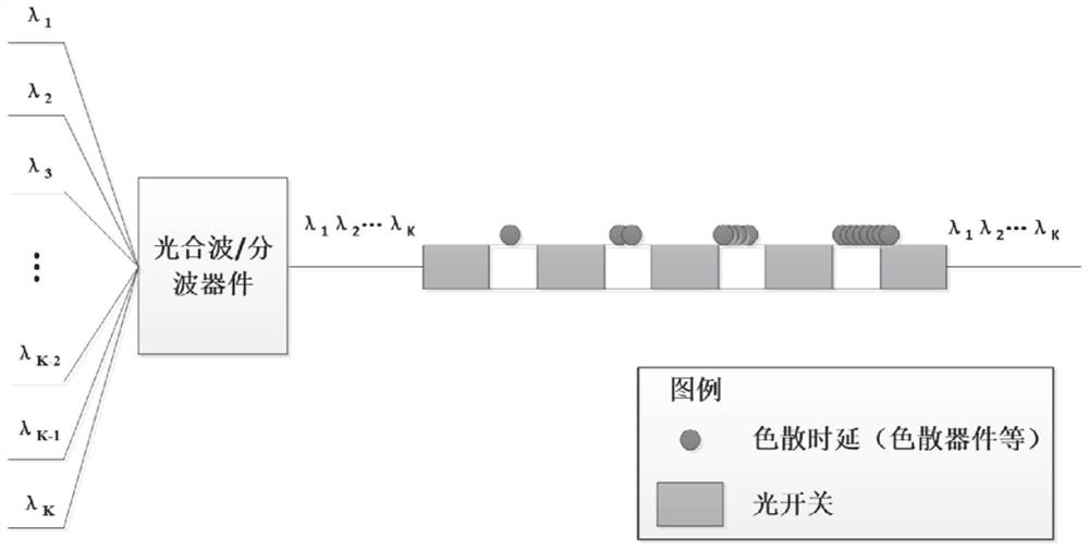
[0054] Such as figure 1 As shown, this embodiment provides an optical beam forming method of an optically controlled phased array radar, the forming method is based on a beam forming system of an optically controlled phased array radar, and the system includes several first optical multiplexers / demultiplexing device and several groups of optical time delay components, and also includes a second optical multiplexer / demultiplexer, one end of each group of optical delay components is connected to a first optical multiplexer / demultiplexer, and the other end is connected to the second optical multiplexer wave / demultiplexer; each group of optical delay components includes an optical dispersion delay component and an optical transmission delay component, and the optical dispersion delay component includes a number of dispersion delay devices and optical switches arranged at intervals, and the optical transmission delay component It includes several transmission delay devices and op...

Embodiment 2

[0101] This embodiment provides a beamforming method of an optically controlled phased array radar, the method is based on the beamforming system in Embodiment 1, when the first optical multiplexing / demultiplexing device and the second optical multiplexing / demultiplexing When all the devices are optical wave splitting devices, the beam forming system realizes the emission of the light beam, and the realization of the emission of the light beam specifically includes the following steps:

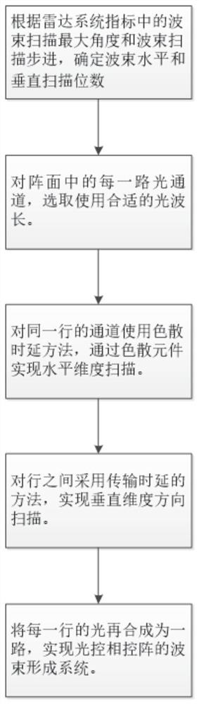
[0102] According to the maximum beam scanning angle and beam scanning step in the radar system index, determine the beam scanning horizontal bit and the beam scanning vertical bit;

[0103] Determine the optical wavelength or optical frequency of each optical channel in the front;

[0104] The beam enters the second optical demultiplexing device, decomposes the optical wavelength or optical frequency, and enters different optical delay components respectively;

[0105] Each optical channel is...


PUM


Abstract

The invention discloses a radar beam forming system, which comprises a plurality of first optical wave combining/dividing devices, a plurality of groups of optical time delay components and a second optical wave combining/dividing device, and is characterized in that one end of each group of optical time delay components is connected with one first optical wave combining/dividing device, and the other end of each group of optical time delay components is connected with the second optical wave combining/dividing device; and each group of optical time delay assemblies comprises an optical dispersion time delay assembly and an optical transmission time delay assembly, the optical dispersion time delay assembly comprises a plurality of dispersion time delay devices and optical switches which are arranged at intervals, and the optical transmission time delay assembly comprises a plurality of transmission time delay devices and optical switches which are arranged at intervals. According to the method, on the premise that the functionality of the radar is kept unchanged, the number of devices, the module size, the power consumption, the cost budget and the like are greatly reduced, and the larger the array plane scale is, the larger the reduction amplitude is.

Description

technical field [0001] The invention relates to the radar field, in particular to an optical beam forming system and a transmitting and receiving method based thereon. Background technique [0002] With the development of radar in the direction of integration of detection, dry, detection and communication, its bandwidth is constantly increasing, and its carrier frequency is also constantly increasing. Photonic technology, with its advantages of large bandwidth, low loss, anti-electromagnetic interference, etc., avoids traditional electrical constraints, and has received more and more attention. Among them, the optical beamforming system that can realize true delay is one of the core technologies. [0003] At present, there are mainly two solutions for the beamforming of optically controlled phased arrays, one is the transmission delay method, and the other is the dispersion delay method. [0004] transmission delay method (such as figure 2 As shown), it refers to changing...

Claims


Application Information

Patent Timeline
Patent Type & Authority Applications(China)
IPC IPC(8): G01S7/02
CPCG01S7/02
Inventor 邵光灏张国强谈宇奇
Owner CHINA ELECTRONICS TECH GRP CORP NO 14 RES INST
Why Eureka
Try Eureka