
A method and system for extracting common imaging point gathers in angle domain of seismic data

A technology for common imaging point gathers and seismic data, which is applied in the field of seismic data angle domain common imaging point gather extraction, can solve the problems of unbalanced amplitude, limited acquisition aperture, and low resolution of angle domain common imaging point gathers, etc. To achieve the effect of improved accuracy, high signal-to-noise ratio and high resolution

Active Publication Date: 2022-02-18
CHINA UNIV OF PETROLEUM (EAST CHINA)
View PDF0 Cites 0 Cited by
  • Summary
  • Abstract
  • Description
  • Claims
  • Application Information

AI Technical Summary

Problems solved by technology

However, due to factors such as inaccurate velocity, limited acquisition aperture, uneven illumination, and inaccurate migration operators, the angle-domain common imaging point gathers extracted based on current existing methods have low resolution, unbalanced amplitude, and low The wave number artifact is serious, which has a great impact on subsequent data processing and interpretation, making it difficult to be directly used in actual production, and making it difficult to take advantage of the angle-domain common imaging point gather

Method used


Image

  • A method and system for extracting common imaging point gathers in angle domain of seismic data
  • A method and system for extracting common imaging point gathers in angle domain of seismic data
  • A method and system for extracting common imaging point gathers in angle domain of seismic data

Examples


example 1

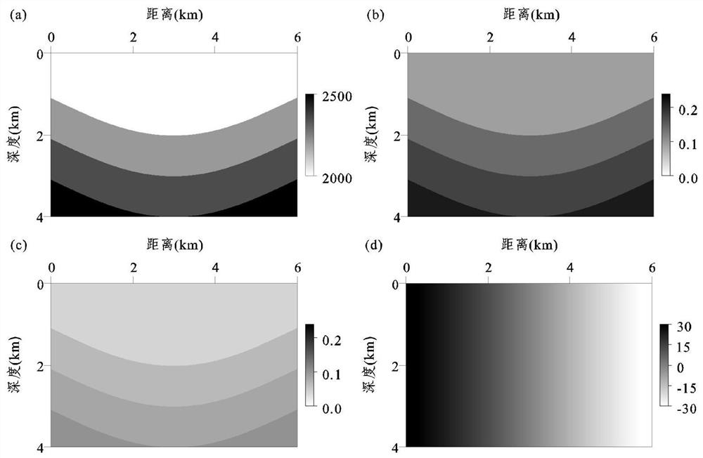
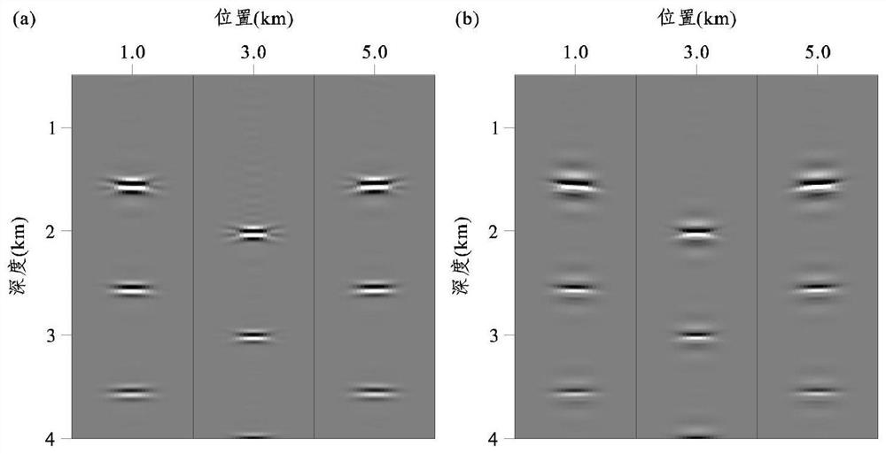
[0133] figure 2 is a two-dimensional layered medium model, (a) P-wave migration velocity model v p , (b) the first anisotropic parameter model ε, (c) the second anisotropic parameter model δ, (d) the structural dip angle model θ. The model has a depth of 4km and a lateral width of 6km. The spatial grid size used for offset is 10m, a total of 41 shots, the initial shot point is located at the left end of the model, the shot point is placed on the surface, the shot interval is 150m, each shot can receive up to 641 channels, the minimum offset distance is 0km, and the maximum offset distance 3.2km, track spacing 10m, recording time length 4.0s, time step 1ms, the main frequency of 15Hz is used as the source time function of the Lake wavelet. image 3 yes figure 2 The local offset domain common imaging point gather of the shown 2D layered medium model: where, image 3 (a) is the common imaging point gather in the local offset domain obtained by the traditional method, imag...

example 2

[0135] Figure 6 is the anisotropic Marmousi-2 model provided by the present invention, (a) P-wave migration velocity model v p , (b) the first anisotropic parameter model ε, (c) the second anisotropic parameter model δ, (d) the structural dip angle model θ. This model is one of the international standard models to verify the effects of various imaging methods. The model has a depth of 5.4km and a lateral width of 27.2km. The spatial grid size used for the offset is 10m, with a total of 109 shots. The initial shot point is located at 2.8km from the model, and the shot point is placed on the surface. The offset distance is 0m, the maximum offset distance is 2500m, the track spacing is 10m, the recording time length is 5.5s, and the time step is 1ms. The Reich wavelet with a main frequency of 30Hz is used as the source time function. Figure 7 yes Figure 6 The seismic record section of the anisotropic Marmousi-2 model shown: where, Figure 7 (a) the observation log of the ...


PUM


Abstract

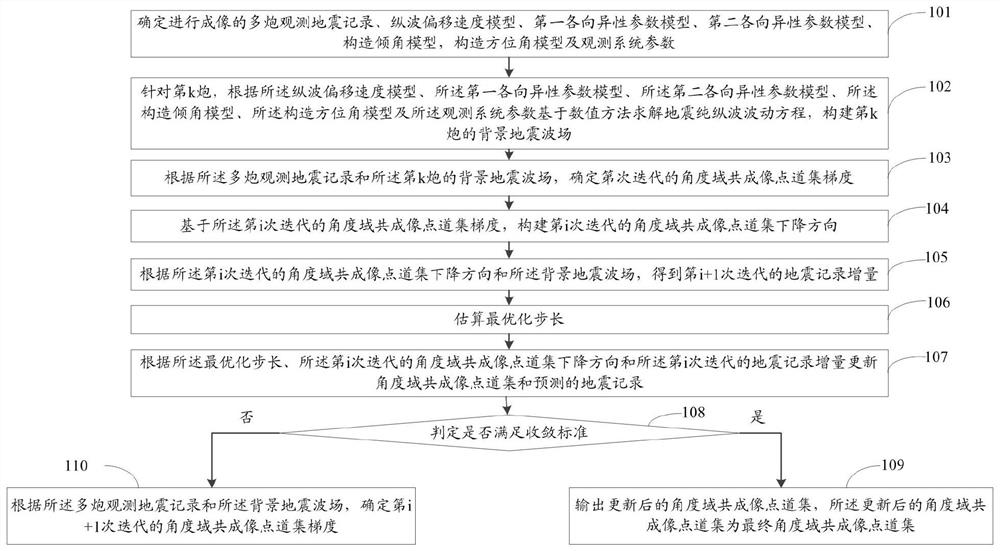
The invention relates to a method and system for extracting seismic data angle domain co-imaging point gathers. The method includes: solving the seismic pure longitudinal wave equation based on the numerical method, and constructing the background seismic wave field of the kth shot; determining the angle domain common imaging point gather gradient of the ith iteration; constructing the angle domain common imaging point trace of the ith iteration According to the descending direction and the background seismic wave field, the seismic record increment of the ith iteration is obtained; the optimal step size is estimated; according to the optimized step size, the descending direction of the i-th iteration’s angle-domain common imaging point gather and The seismic records of the iterative iteration update the angle domain common imaging point gather and the predicted seismic records incrementally; determine whether the convergence criterion is met; if so, output the updated angle domain common imaging point gather; if not, determine the first The angle-domain common image point gather gradient of the i+1 iteration. The invention can obtain the common imaging point gather in the angle domain with high precision, high resolution, high signal-to-noise ratio and amplitude fidelity.

Description

technical field [0001] The invention relates to the field of imaging processing of seismic data co-imaging point gathers, in particular to a method and system for extracting seismic data angle domain common imaging point gathers. Background technique [0002] Common imaging point gather is a kind of intermediate data obtained by prestack migration imaging method. The information reflecting the velocity of subsurface medium and lithology contained in the common imaging point gather is a powerful tool for migration velocity analysis and seismic amplitude analysis. In migration velocity analysis, the residual moveout of the common imaging point gather effectively reflects the error of the migration velocity field. When the velocity field is accurate, the event axis of the common imaging point gather is horizontal. When the velocity field is inaccurate, The common imaging point gather event is curved, and the degree of curvature is related to the velocity field error. Through t...

Claims


Application Information

Patent Timeline
Patent Type & Authority Patents(China)
IPC IPC(8): G01V1/36
CPCG01V1/36G01V2210/512
Inventor 谷丙洛黄建平
Owner CHINA UNIV OF PETROLEUM (EAST CHINA)
Learn More