
Passive micro light-emitting diode matrix device with uniform luminance

A micro-light-emitting diode technology with uniform brightness, applied in semiconductor devices, electrical components, circuits, etc., can solve problems such as difficulty in uniform brightness and uneven brightness, and achieve the effect of improving brightness uniformity and compensating series resistance

Pending Publication Date: 2021-02-02
薛富盛
View PDF8 Cites 2 Cited by
  • Summary
  • Abstract
  • Description
  • Claims
  • Application Information

AI Technical Summary

Problems solved by technology

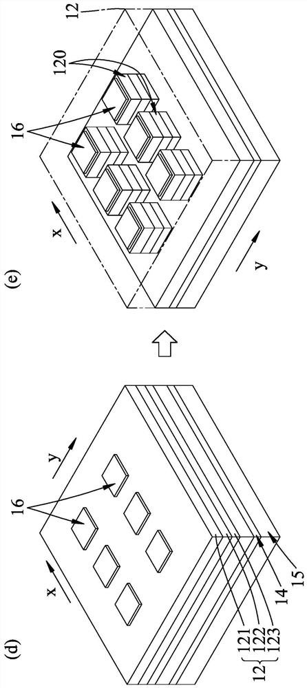
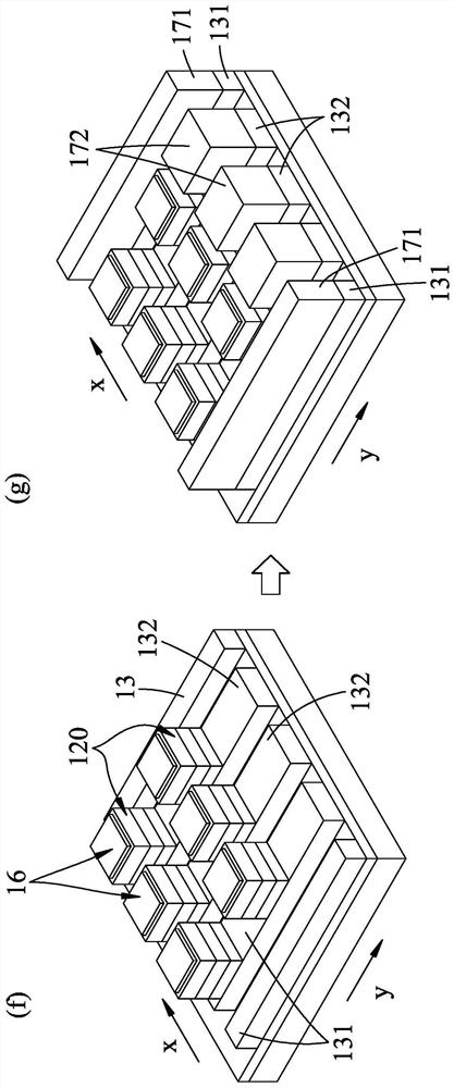
Therefore, the brightness of the micro-LED crystal grains 120 in the row direction y gradually decreases from the adjacent second thickened metal layer 172 to the row direction y, and the brightness is not uniform.
[0014] further by Image 6 Shown [with reference to Figure 4 Step (i)], it can be seen that although the three output power curves of the corresponding micro-LED crystal grains 120 on the 3rd, 33rd and 61st rows of the existing passive micro-LED display 1 tend to overlap; However, the aforementioned three output power curves decrease from the first row of pixels to the 15th row of pixels, making it difficult to uniformize the brightness

Method used


Image

  • Passive micro light-emitting diode matrix device with uniform luminance
  • Passive micro light-emitting diode matrix device with uniform luminance
  • Passive micro light-emitting diode matrix device with uniform luminance

Examples


Embodiment Construction

[0061] Before the present invention is described in detail, it should be noted that in the following description, similar elements are denoted by the same numerals.

[0062] refer to Figure 7 to Figure 11 A first embodiment of the passive micro-light emitting diode array device with uniform brightness of the present invention is used for electrical bonding to a printed circuit board (such as a flexible printed circuit board) that is bonded to a driver chip (not shown) 9 , which includes a micro light emitting diode array 2 and an external circuit component 3 .

[0063] Such as Figure 7 and Figure 8 As shown, the micro light emitting diode array 2 of the first embodiment of the present invention is essentially composed of a substrate 21 having an array setting surface 211, a plurality of micro light emitting diode arrays 22 and an insulating layer 23 for the array; wherein, the The substrate 21 is a double-sided polished sapphire substrate.

[0064] The micro-light emitt...


PUM


Abstract

A passive micro light-emitting diode matrix device with uniform luminance includes a micro light-emitting diode array and an external circuit assembly. The micro light-emitting diode array comprises asubstrate, a plurality of micro light-emitting arrays which are distributed on the substrate at intervals along the Y direction, and an insulating layer for the arrays. Each micro-light-emitting array is sequentially provided with a first layer, a plurality of spaced light-emitting layers, a second layer, a first inner electrode layer and a second inner electrode layer, wherein the first layer extends in the X direction, and the second inner electrode layer extends in the first layer and is provided with a base part surrounding the light-emitting layers at intervals and a protruding part protruding from the base part. The array covers the substrate with an insulating layer and exposes the first and second inner electrode layers. The external circuit assembly comprises a carrier plate facing the substrate, a first external circuit and a second external circuit which are spaced in the Y direction and the X direction and extend to the carrier plate in the X direction and the Y direction,a circuit insulating layer exposing the first external circuit and the second external circuit, and an electrical bonding unit bonded to the first external circuit, the second external circuit, the first internal electrode layer and the second internal electrode layer. By means of the external circuit assembly on the carrier plate, the area of the array arrangement surface can be effectively utilized.

Description

technical field [0001] The invention relates to a passive micro light emitting diode (Micro-LED) array device, in particular to a passive micro light emitting diode array device with uniform brightness. Background technique [0002] With the evolution of science and technology and the demand of the market, related research on various types of thin, light and small electronic devices has become the mainstream of the development of major electronics factories at this stage. The aforementioned light, thin and miniaturized electronic devices can be seen as Micro-LED displays composed of micro-LEDs. [0003] The inventor disclosed an existing passive micro-LED display 1 (see Figure 4 ). The manufacturing method of this existing passive micro-light-emitting diode display 1 is to refer to in sequence Figure 1 to Figure 4 Shown a step (a), a step (b), a step (c), a step (d), a step (e), a step (f), a step (g), a step (h) and a step (i) prepared. [0004] Such as figure 1 As ...

Claims


Application Information

Patent Timeline
Patent Type & Authority Applications(China)
IPC IPC(8): H01L27/15H01L33/38
CPCH01L27/156H01L33/38H01L25/0753H01L33/62H01L24/16H01L24/32H01L2224/16227H01L2224/32227H01L2224/83851H01L2924/12041H01L2224/13111H01L2224/17106H01L24/13H01L2224/81192H01L2224/13013H01L2224/13017H01L2224/13016H01L24/29H01L2224/29017H01L2224/29016H01L2224/29013H01L24/14H01L2224/14131H01L2224/1411H01L2224/14177H01L24/73H01L2224/14051H01L2224/73103H01L2224/14151H01L2224/30151H01L24/30H01L2224/2919H01L2224/32225H01L2224/33181H01L2224/73253H01L2224/92242H01L2224/9211H01L2224/04026H01L24/05H01L24/33H01L24/81H01L24/83H01L2224/83192H01L24/92H01L2224/95H01L24/17H01L2224/131H01L2224/05686H01L2924/00014H01L2924/014H01L2924/01079H01L2924/01029H01L2924/01047H01L2924/00012H01L2224/81H01L2224/83H01L2924/0549H01L2924/0543H01L2924/01049H01L2924/0544H01L2924/0105H01L33/486
Inventor 武东星洪瑞华陈柏玮
Owner 薛富盛
Learn More