Atomizer with integrated atomization assembly

An atomization component and one-piece technology, applied in therapeutic nebulizers, inhalers, tobacco, etc., can solve the problems of inconvenient automatic production, inability to seal with glass fiber rope or cotton rope, low production efficiency, etc. Automated production, good liquid storage and guiding performance, and the effect of improving production efficiency

Pending Publication Date: 2021-02-05
HUIZHOU HAPPY VAPING TECH LTD
View PDF0 Cites 5 Cited by
  • Summary
  • Abstract
  • Description
  • Claims
  • Application Information

AI Technical Summary

Problems solved by technology

[0004] In the existing electronic atomization equipment, the material used as the conductive liquid in the atomizer is generally a long strip of glass fiber rope or cotton rope, and the heating wire is directly wound on the glass fiber rope or cotton rope. Due to its small size, The liquid storage performance is poor. During the heating process, it is easy to burn due to the small amount of liquid storage and the untimely conduction of the atomized liquid, resulting in burnt smell, resulting in poor user experience.
In addition, in the structure of the atomizer using glass fiber rope or cotton rope as the liquid guide, the glass fiber rope or cotton rope is generally erected horizontally above the atomization seat, and the two ends of the glass fiber rope or cotton rope extend into the liquid storage chamber. Absorb and conduct the atomized liquid. Generally, this structure cannot completely seal the liquid storage chamber and the glass fiber rope or cotton rope. When the user has a large suction force, it is easy to cause liquid leakage.
In addition, in production, it is necessary to wrap the glass fiber rope or cotton rope around the heating wire and install it on the atomizer seat, and then put the atomizer seat and other accessories into the atomizer housing one by one for assembly. The structure is complex and inconvenient to assemble. Low production efficiency and not easy to automate production

Method used


Image

  • Atomizer with integrated atomization assembly
  • Atomizer with integrated atomization assembly
  • Atomizer with integrated atomization assembly

Examples


Embodiment

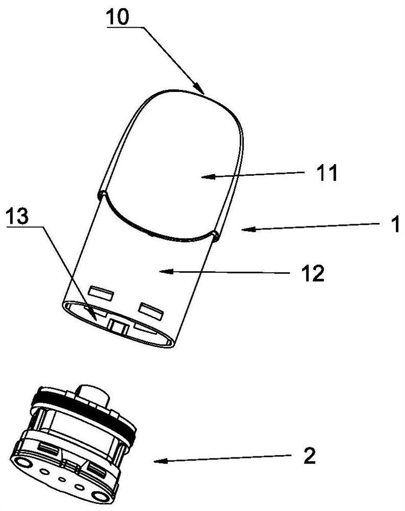
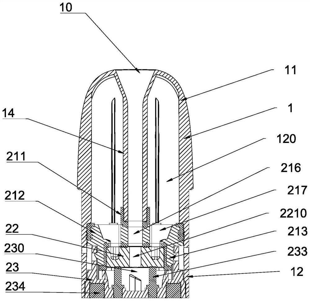
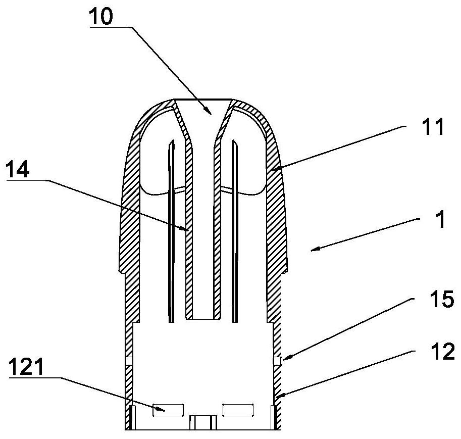
[0061] like Figure 1-Figure 3 As shown, the atomizer with an integrated atomization assembly of the present invention is composed of a housing 1 and an integrated atomization assembly 2. The housing 1 has upper and lower ends, that is, the suction nozzle end 11 and the connecting end 12, and the suction nozzle The end 11 is provided with a suction port 10, and the suction port 10 is integrally formed with a mist outlet pipe 14 extending inward. 1. Connect to the battery assembly (not shown in the figure) through the connection terminal 12 to form an electronic atomization device. The housing 1 is provided with an integrated atomization assembly 2 , and the integrated atomization assembly 2 is loaded into the housing 1 through the opening 13 . The one-piece atomization component 2 can be assembled conveniently first, and then put into the casing 1 after the assembly is completed, so that not only the installation quality is reliable, but also the production efficiency can be ...


PUM


Abstract

The invention discloses an atomizer with an integrated atomization assembly. The atomizer comprises a shell and the integrated atomization assembly, wherein the shell comprises a suction nozzle end and a connecting end, the suction nozzle end is provided with a suction port, the connecting end is provided with an opening, the shell is connected with a battery assembly through the connecting end toform electronic atomization equipment, and the integrated atomization assembly is mounted in the shell from the opening. The integrated atomization assembly comprises an atomization core base, an atomization core and a base from top to bottom, wherein the atomization core base is connected with the base, an upward-concave groove is formed in the lower portion of the atomization core base, the atomization core is mounted in the groove, the atomization core comprises an atomization core body used for absorbing atomization liquid and a heating resistor used for heating the atomization liquid, and the atomization core body is provided with an atomization channel. An air inlet cavity communicating with the atomization channel is further formed between the atomization core and the base, and thebase blocks the opening of the shell. The atomizer has the beneficial effects that during heating atomization, atomization is uniform, the atomization effect is good, scorched smell caused by scorching is not liable to generate, the structure is firm, deformation is avoided, and the phenomena of liquid leakage and gas leakage are avoided.

Description

technical field [0001] The present invention relates to the technical field of electronic atomization equipment, and more specifically, the present invention relates to an atomizer with an integrated atomization assembly. Background technique [0002] Electronic atomization equipment generally includes a battery assembly and an atomizer. The battery assembly is equipped with a battery that supplies power to the atomizer. The atomizer includes a heating unit that can atomize the solution to be atomized into vapor when it is powered on. mist for the user to inhale into the mouth. [0003] Electronic atomization equipment specifically includes medical drug atomization equipment, etc., and its basic task is to provide a heating process to convert the atomization liquid or liquid medicine stored in the electronic atomization equipment into vapor mist, aerosol, steam, etc. [0004] In the existing electronic atomization equipment, the material used as the conductive liquid in the...

Claims


Application Information

Patent Timeline
Patent Type & Authority Applications(China)
IPC IPC(8): A61M15/06A61M15/00A61M11/00A24F40/48A24F40/40A24F40/10
CPCA61M15/06A61M15/0001A61M11/00A24F40/48A24F40/40A24F40/10A24F40/485A61M11/042A61M15/0021A61M2016/0039A61M2016/0024
Inventor 林光榕郑贤彬
Owner HUIZHOU HAPPY VAPING TECH LTD
Why Eureka
Try Eureka