
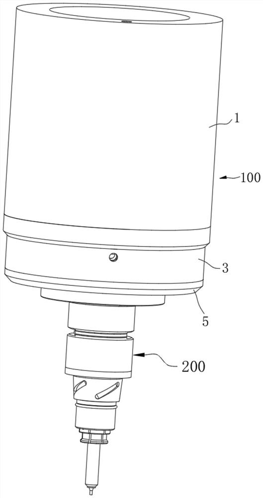
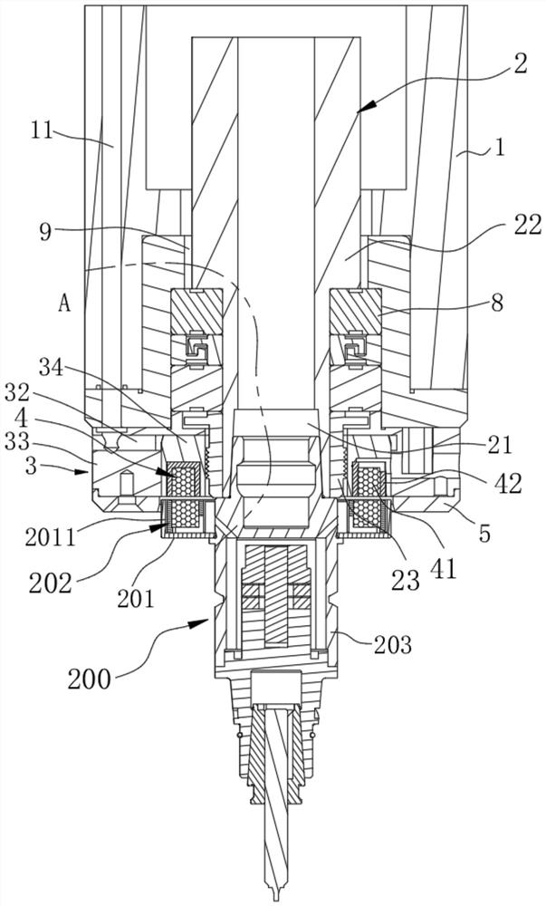
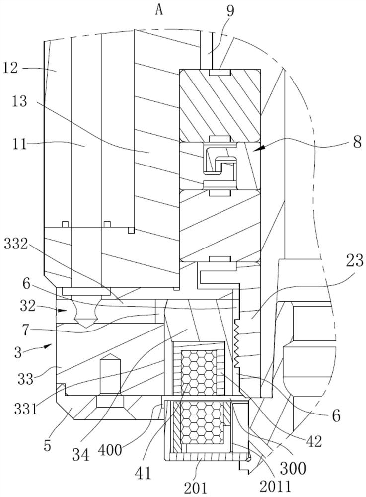
Ultrasonic machining device and ultrasonic spindle thereof

An ultrasonic and spindle technology, applied in the direction of metal processing equipment, metal processing machinery parts, manufacturing tools, etc., can solve the problems of unstable electrical conduction, affecting the processing effect of tools, and low installation accuracy, so as to achieve stable electrical conduction Reliable, improve processing effect, improve the effect of assembly accuracy

Active Publication Date: 2021-02-05
CONPROFE MACHINE TOOLS CO LTD +1
View PDF11 Cites 3 Cited by
  • Summary
  • Abstract
  • Description
  • Claims
  • Application Information

AI Technical Summary

Problems solved by technology

[0004] At present, the ultrasonic wireless transmitting device is generally suspended by a hoop or installed outside the main shaft through a mounting bracket, and the installation accuracy is low, resulting in unstable electrical conduction between it and the ultrasonic wireless receiving device, which affects the processing effect of the tool

Method used


Image

  • Ultrasonic machining device and ultrasonic spindle thereof
  • Ultrasonic machining device and ultrasonic spindle thereof
  • Ultrasonic machining device and ultrasonic spindle thereof

Examples


Embodiment Construction

[0058] Preferred embodiments of the present application will be described in detail below with reference to the accompanying drawings. Those skilled in the art will appreciate that these descriptions are only descriptive and exemplary, and should not be construed as limiting the protection scope of the present application.

[0059] First of all, it should be noted that the orientations of top, bottom, upward, and downward mentioned in this article are defined relative to the directions in each drawing, and they are relative concepts, and therefore can be It changes in different positions and different practical states. Accordingly, these or other orientations should not be construed as limiting terms.

[0060] It should be noted that the term "comprising" does not exclude other elements or steps, and "a" or "an" does not exclude a plurality.

[0061] In addition, it should also be noted that for any single technical feature described or implied in the embodiments herein, or ...


PUM


Abstract

The invention relates to the technical field of ultrasonic machining, and discloses an ultrasonic machining device and an ultrasonic spindle thereof. The ultrasonic machining device comprises a spindle shell, a rotating shaft assembly, a front end cover and an ultrasonic wireless transmitting device, wherein the rotating shaft assembly is rotationally arranged in the spindle shell, the front end of the rotating shaft assembly protrudes out of the front end face of the spindle shell, and a mounting hole is formed in the front end face of the rotating shaft assembly; the front end cover is installed at the front end of the spindle shell and is annularly arranged on the periphery of the rotating shaft assembly, the rear end face of the front end cover is attached to the front end face of thespindle shell, and a first containing groove annularly formed in the rotating shaft assembly is formed in the front end face of the front end cover; and the ultrasonic wireless transmitting device isarranged in the first containing groove and comprises a transmitting coil and a transmitting ferrite. According to the ultrasonic machining device and the ultrasonic spindle thereof, the device has good machining precision and machining efficiency, the device is suitable for machining working conditions in a larger range, and more materials can be machined.

Description

technical field [0001] The invention relates to the technical field of ultrasonic processing, in particular to an ultrasonic processing device and an ultrasonic spindle. Background technique [0002] Introducing a high-frequency vibration machining mechanism in the process of machining operations can not only improve the surface roughness of the cutting surface and improve machining accuracy, but also reduce cutting resistance and increase the life of the tool, so it is gradually widely used. Ultrasonic spindles are one such application. [0003] The existing ultrasonic spindle includes fixed parts, rotating parts, bearings and ultrasonic transmission devices. Wherein, the fixed part includes related parts such as the housing and the front end cover. Rotating parts include related parts such as rotating shafts. The ultrasonic transmission device may be an ultrasonic wireless transmission device or an ultrasonic wired transmission device. [0004] At present, the ultrason...

Claims


Application Information

Patent Timeline
Patent Type & Authority Applications(China)
IPC IPC(8): B23B19/02B23Q11/00
CPCB23Q1/70B23Q11/00
Inventor 颜炳姜李伟秋
Owner CONPROFE MACHINE TOOLS CO LTD
Learn More