Square wood block drilling equipment
A technology for drilling equipment and wood blocks, which is applied to fixed drilling machines and other directions, can solve the problems of unreachable, easy deviation of the position of wood blocks, and difficulty in fixing its position, and achieves the effect of improving drilling accuracy.
- Summary
- Abstract
- Description
- Claims
- Application Information
AI Technical Summary
Problems solved by technology
Method used
Image

Examples
Embodiment 1
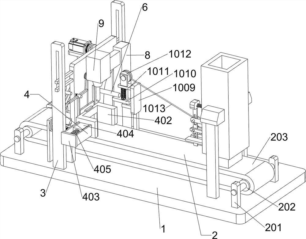
[0066]A square block drilling equipment, such asfigure 1 As shown, it includes a bottom plate 1, a transmission assembly 2, a second support frame 3, a clamping assembly 4, a rising assembly 5, a clamp rod 6, a limit assembly 7, a sixth support frame 8 and a drilling machine 9. The top of the bottom plate 1 A transmission assembly 2 is provided. The top left side of the bottom plate 1 is provided with a second support frame 3 symmetrically, a clamping assembly 4 is connected between the second support frames 3, a rising assembly 5 is provided on the top left side of the bottom plate 1, and the clamping assembly 4 A limit assembly 7 and a clamping rod 6 are provided, a sixth support frame 8 is provided on the top left rear side of the bottom plate 1, and a drilling machine 9 is provided on the top front side of the sixth support frame 8.
[0067]When you need to drill a square plank, you can use this equipment. You can first start the drilling machine 9 to work, and the staff can put th...
Embodiment 2
[0069]On the basis of Example 1, such asfigure 1 withfigure 2 As shown, the transmission assembly 2 includes a first support frame 201, a roller 202, a conveyor belt 203, and a first servo motor 204. A first support frame 201 is provided around the top of the bottom plate 1, and the first support frame 201 rotates between the front and rear sides. A roller 202 is connected to the roller 202, a conveyor belt 203 is connected between the rollers 202, a first servo motor 204 is provided on the top left rear side of the bottom plate 1, and the output shaft of the first servo motor 204 is connected to the rear end of the left roller 202.
[0070]Place the wooden board on the conveyor belt 203, and then start the first servo motor 204 to work. The output shaft of the first servo motor 204 rotates the left roller 202 to rotate, thereby driving the conveyor belt 203 to rotate. The conveyor belt 203 rotates to drive the wooden board to move to the left. When moving to the left to the clamping a...
Embodiment 3
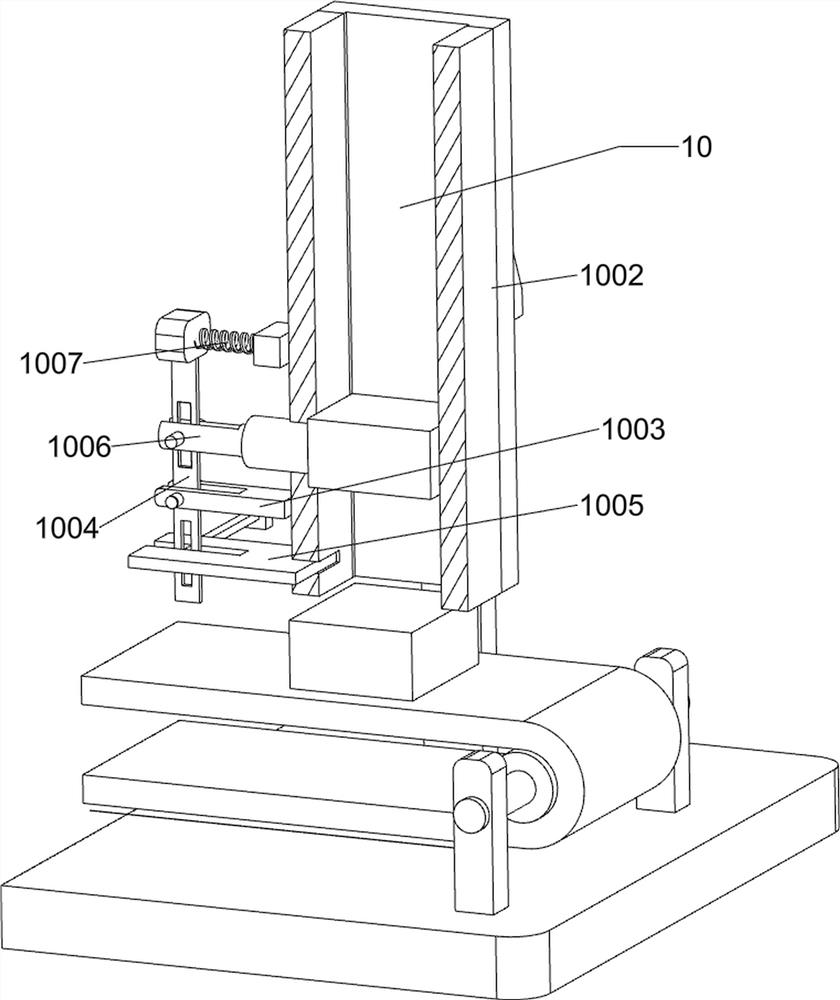
[0078]On the basis of Example 2, such asfigure 1 ,figure 2 withimage 3 As shown, the blanking assembly 10 is also included. The blanking assembly 10 includes a seventh support frame 1001, a material guide frame 1002, a support rod 1003, a first rotating rod 1004, a baffle plate 1005, a pressure rod 1006, and a fourth spring 1007, connecting rod 1008, eighth support frame 1009, support block 1010, fifth spring 1011, second guide wheel 1012 and second pull rope 1013, a seventh support frame 1001 is provided symmetrically on the top right side of bottom plate 1, and seventh support A guide frame 1002 is connected between the racks 1001. The left side of the guide frame 1002 is provided with a support rod 1003. The support rod 1003 is provided with a first rotating rod 1004 that can rotate on the left side, and a sliding type is provided on the lower side of the first rotating rod 1004. The stopper 1005, the stopper 1005 and the guide frame 1002 slidingly fit, the rear end of the stoppe...
PUM
 Abstract
Description
Claims
Application Information
 - Generate Ideas
- Intellectual Property
- Life Sciences
- Materials
- Tech Scout
- Unparalleled Data Quality
- Higher Quality Content
- 60% Fewer Hallucinations
Browse by: Latest US Patents, China's latest patents, Technical Efficacy Thesaurus, Application Domain, Technology Topic, Popular Technical Reports.
© 2025 PatSnap. All rights reserved.Legal|Privacy policy|Modern Slavery Act Transparency Statement|Sitemap|About US| Contact US: help@patsnap.com