Glove taking-off device

A technology for picking up devices and gloves, which is applied in the field of glove production equipment, can solve the problems that the gripping action of the gripper is difficult to accurately control, the working stability of the picking device is poor, and the production and use of users are affected, and the control is convenient and the work is stable. Good, stable stroke effect

Pending Publication Date: 2021-02-05
山东荣程自动化科技有限公司
View PDF0 Cites 0 Cited by
  • Summary
  • Abstract
  • Description
  • Claims
  • Application Information

AI Technical Summary

Problems solved by technology

However, because the jaws need to rotate, this leads to a complicated pipeline for conveying compressed air, and it is difficult to accurately control the gripping action of the jaws. The stability of the gripping jaws depends entirely on the stability of the compressed air. The most important thing is Due to the high-frequency movement of the jaws, the service life of the jaws is generally very short, which not only affects the user's use, but also has very high repair and maintenance costs, resulting in poor working stability and high failure rate of the existing picking device, which affects users. normal production and use

Method used


Image

  • Glove taking-off device
  • Glove taking-off device
  • Glove taking-off device

Examples


Embodiment 1

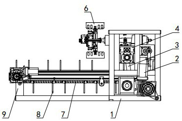
[0031] Such as figure 1 As shown: the rotating device is slidably installed on the frame 1, and the lifting device is arranged on the frame 1 on the lower side of the rotating device. Multiple, thereby improving the extraction efficiency of the equipment.

[0032] The lower side of the clamping device is provided with a conveying device 7, and the conveying device 7 is arranged horizontally. The lower side of one end of the conveying device 7 away from the frame 1 is provided with a support profile 9, and the other end extends into the frame 1 and is arranged on the clamping The lower side of the device, the upper side of the delivery device 7 near the end of the frame 1 is provided with a lift cylinder, the lift cylinder is installed on the frame 1 and vertically arranged, the piston rod of the lift cylinder is connected with the delivery device 7, and drives its Swing, so that the height of the conveying device 7 can be adjusted according to the thickness of the glove stack...

Embodiment 2

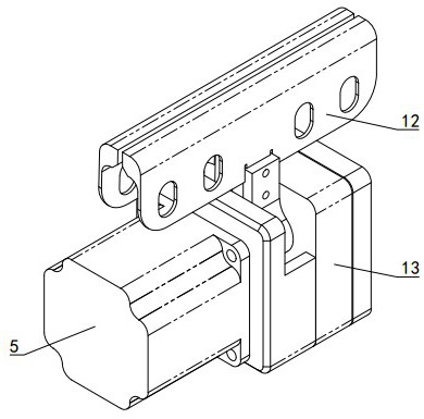
[0045] Such as Figure 7 As shown: the difference between embodiment 2 and embodiment 1 is that the conveying device 7 is a conveying belt 23, and a synchronous belt is fixed inside the conveying belt 23, and the conveying motor 17 drives the synchronous belt to rotate, thereby realizing the rotation of the conveying belt 23, and the baffle plate 8. It can effectively ensure that piles of gloves will not be overturned, and the overall conveyor belt 23 will not be misplaced and ensure that the gloves will not be polluted by accumulated dust during transportation.

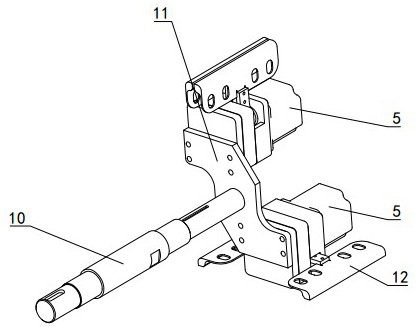
[0046] Such as Figure 8 As shown: each lifting frame 18 is only provided with a hand model seat, the lower side of the lifting frame 18 is provided with a vertical mounting rod, and the hand model mounting plate 19 is coaxial and rotatably mounted on the mounting rod, and the hand model mounting plate 19 is slidingly connected with the installation rod, the diameter of the lower end of the installation rod is large...


PUM


Abstract

The invention relates to a glove taking-off device, and belongs to the technical field of glove production equipment. The glove taking-off device comprises a lifting device, a rotating device and a clamping device connected with the rotating device, and the lifting device is connected with the clamping device and drives the clamping device to ascend and descend. The glove taking-off device is characterized in that the clamping device comprises two symmetrically-arranged clamping plates (12) and a clamping motor (5), and an output shaft of the clamping motor (5) is connected with the two clamping plates (12) at the same time through a transmission mechanism and drives the two clamping plates (12) to synchronously swing in the opposite directions. The clamping plates of the glove taking-offdevice are driven by the clamping motor, so that clamping and loosening of the clamping plates are achieved, complex pipelines and valves are not needed, only a circuit needs to be connected through asliding ring, and compared with air cylinder driving, control is convenient, the clamping plates are stable in action and reliable in clamping, and the taking-off device is low in failure rate and good in working stability, so that production efficiency is improved.

Description

technical field [0001] A glove picking device belongs to the technical field of glove production equipment. Background technique [0002] In the glove production line, after the glove is formed on the hand mold, the equipment is used to roll the glove down from the hand mold to realize the initial separation of the glove and the hand mold, and then it is necessary to use the glove jaw to completely remove the glove from the hand mold. Most of the grippers are of pneumatic structure, so they need to be driven by compressed air. After the grippers pick up the gloves, they need to be stacked on the lower conveyor belt. Usually, the grippers are connected to the motor and rotate with the motor, thus realizing the gripper Movement in vertical position. However, because the jaws need to rotate, this leads to a complicated pipeline for conveying compressed air, and it is difficult to accurately control the gripping action of the jaws. The stability of the gripping jaws depends ent...

Claims


Application Information

Patent Timeline
Patent Type & Authority Applications(China)
IPC IPC(8): B29C41/42B29L31/48
CPCB29C41/42B29L2031/4864
Inventor 崔路志耿世和
Owner 山东荣程自动化科技有限公司
Why Eureka
Try Eureka